Hydraulic drive system

a technology of hydraulic drive system and hydraulic pressure, which is applied in the direction of fluid coupling, servomotor, coupling, etc., can solve the problems of difficult for the operator to adjust the work implement to a desired height, the crawler track rises suddenly from the ground, and the hydraulic pressure in the closed hydraulic circuit tends to rise rapidly, so as to facilitate the operator's adjustment of the work implement's position, improve the work efficiency of the work implement, and facilitate the effect of lowering the work implemen

Active Publication Date: 2015-06-25
KOMATSU LTD
View PDF0 Cites 1 Cited by
  • Summary
  • Abstract
  • Description
  • Claims
  • Application Information

AI Technical Summary

Benefits of technology

[0019]In the hydraulic drive system according to the first aspect of the present invention, the second flowpath is connected to the bleed-off flowpath via a throttle when the operation amount of the operating member for lowering the work implement is less than a predetermined operation amount. Thus, a portion of the hydraulic fluid in the second flowpath is bled off into the bleed-off flowpath, and the hydraulic pressure in the second flowpath is maintained at less than the relief pressure. Therefore, the acceleration force to lower the work implement can be supressed. This facilitates the operator's adjusting the position of the work implement to a desired height.
[0020]In the hydraulic drive system according to the second aspect of the present invention, the opening between the second flowpath and the bleed-off flowpath is closed when the operation amount of the operation member is greater than or equal to a predetermined operation amount. Therefore, the work implement can be lowered quickly when the operation amount of the operation member is greater than or equal to a predetermined operation amount. Thus, it is possible to improve the work efficiency of the work implement.
[0021]In the hydraulic drive system according to the third aspect of the present invention, the charge flow rate into the hydraulic fluid flowpath can be reduced. Thus, it is possible to improve the fuel consumption of the drive source.
[0022]In the hydraulic drive system according to the fourth aspect of the present invention, the hydraulic pressure in the second flowpath increases in accordance with the increase in the operation amount of the operation member even when the operation amount of the operation member is smaller than the predetermined operation amount. Thus, it is possible to adjust the operation speed of the work implement using the operation member.

Problems solved by technology

Therefore, the hydraulic pressure in the closed hydraulic circuit tends to rise rapidly even when an operator operates a control in a manner to slowly lower a work implement.
In this case, it can be difficult for the operator to adjust the work implement to a desired height because of the large accelerative force of the work implement.
However, as above described, when the hydraulic pressure in the closed hydraulic circuit rises rapidly, the crawler track rises suddenly from the ground.
The operator can find it difficult to adjust the position of the crawler track to a desired height when the crawler track rises suddenly.

Method used


Image

  • Hydraulic drive system
  • Hydraulic drive system
  • Hydraulic drive system

Examples


first exemplary embodiment

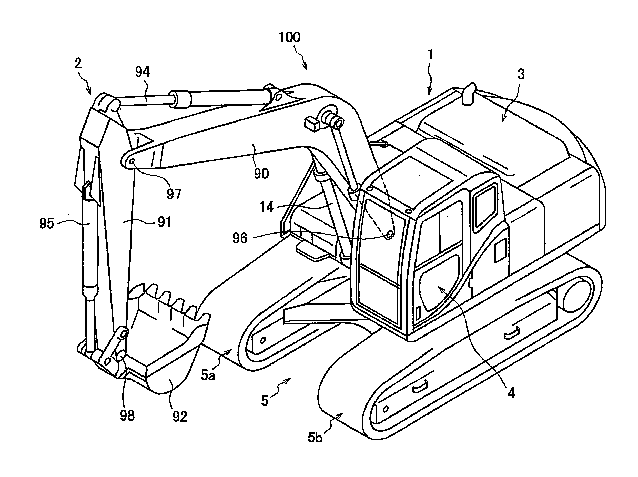
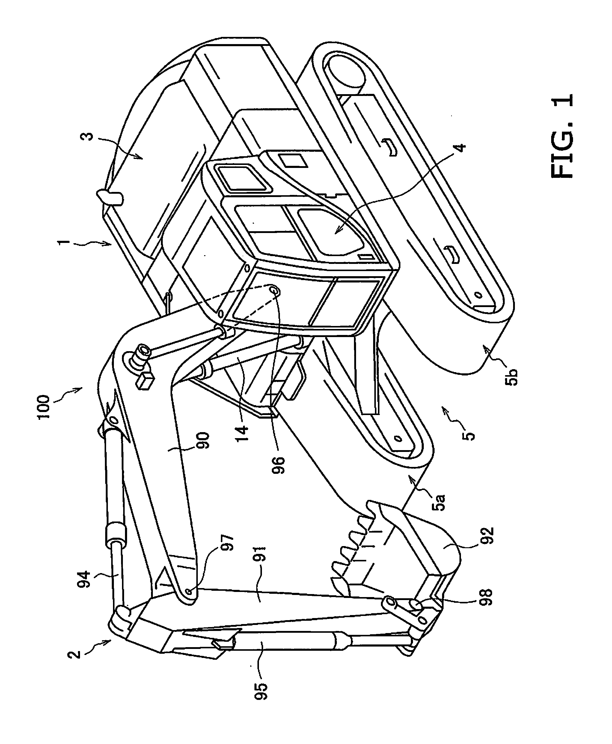
[0035]FIG. 1 is a perspective view of a hydraulic shovel 100 containing the hydraulic drive system according to a first exemplary embodiment of the present invention. The hydraulic shovel 100 includes a vehicle body 1 and a work implement 2. The vehicle body 1 includes an upper revolving unit 3, a cab 4, and an undercarriage 5. The upper revolving unit 3 is mounted on the undercarriage 5. The upper revolving unit 3 is provided on the undercarriage 5 to be rotatable with respect to the undercarriage 5. The upper revolving unit 3 houses apparatus, such as an engine and a hydraulic pump, which are described hereinafter. The cab 4 is located at the front of the upper revolving unit 3. An operating device, which is described hereinafter, is arranged within the cab 4. The undercarriage 5 includes crawler tracks 5a, 5b. The hydraulic shovel 100 travels via the rotation of the crawler tracks 5a, 5b.

[0036]The work implement 2 is attached to the front of the vehicle body 1. The work implemen...

second exemplary embodiment

[0092]FIG. 5 illustrates a hydraulic drive system according to a second exemplary embodiment of the present invention. The hydraulic drive system according to the second exemplary embodiment includes a third bleed-off port 16i in the control valve 16. The third bleed-off port 16i is connected to the second pump flowpath 34 via a third direction control section 48. The third direction control section 48 allows the hydraulic fluid to flow from the second pump flowpath 34 to the third bleed-off port 16i, and prevents the hydraulic fluid from flowing from the third bleed-off port 16i into the second pump flowpath 34.

[0093]Additionally, in the third position state P3, the control valve 16 links the third bleed-off port 16i and the first bypass port 16d via the throttle 17. Accordingly, when the control valve 16 is in the third position state P3 the control valve 16 connects the second pump flowpath 34 to a flowpath 38 via the throttle 17. The flowpath 38 connects the first bypass port 16...

third exemplary embodiment

[0100]FIG. 6 illustrates a hydraulic drive system according to a third exemplary embodiment of the present invention. The hydraulic drive system according to the third exemplary embodiment excludes the second hydraulic pump 13 in the hydraulic drive system according to the first exemplary embodiment. Accordingly, the main pump 10 is configures by a single hydraulic pump (the first hydraulic pump 12). Furthermore, the hydraulic drive system according to the third exemplary embodiment includes a shuttle valve 51.

[0101]The shuttle valve 51 includes a first input port 51a, second input port 51b, a drain port 51c, a first pressure receiver 51d, and a second pressure receiver 51e. The first input port 51a is connected to the first flowpath 15a. The second input port 51b is connected to the second flowpath 15b. More specifically, the first input port 51a is connected to the first pump flowpath 33. The second input port 51b is connected to the second pump flowpath 34. The drain port 51c is ...


PUM


Abstract

A hydraulic fluid flowpath includes a first flowpath and a second flowpath. The first flowpath connects a first pump port and a first chamber in a hydraulic cylinder. The second flowpath connects a second pump port and a second chamber in the hydraulic cylinder. The hydraulic fluid flowpath forms a closed circuit between a hydraulic pump and the hydraulic cylinder. A bleed-off flowpath bleeds off a portion of the hydraulic fluid from the second flowpath. A control valve connects the second flowpath to the bleed-off flowpath via a throttle when an operation amount of an operating member for lowering a work implement is less than a predetermined operation amount so that a hydraulic pressure in second flowpath is maintained at less than a relief pressure. The predetermined operation amount is less than or equal to the maximum operation amount for lowering the work implement.

Description

CROSS-REFERENCE TO RELATED APPLICATIONS[0001]This application is a U.S. National stage application of International Application No. PCT / JP2013 / 075792, filed on Sep. 25, 2013. This U.S. National stage application claims priority under 35 U.S.C. §119(a) to Japanese Patent Application No. 2012-231357, filed in Japan on Oct. 19, 2012, the entire contents of which are hereby incorporated herein by reference.BACKGROUND[0002]1. Field of the Invention[0003]The present invention relates to a hydraulic drive system.[0004]2. Background Information[0005]Machinery, such as hydraulic shovels and wheel loaders, is provided with a work implement that is driven by a hydraulic cylinder. The hydraulic cylinder is supplied with the hydraulic fluid discharged from a hydraulic pump. The hydraulic fluid is supplied to the hydraulic cylinder by way of a hydraulic circuit. For instance, Japanese Laid-Open Patent Application Publication No. 2003-21104 proposes a work implement equipped with a closed hydrauli...

Claims


Application Information

Patent Timeline
Patent Type & Authority Applications(United States)
IPC IPC(8): F15B11/044E02F9/22F15B11/08
CPCF15B11/0445E02F9/2225F15B11/08E02F9/2228E02F9/2235F15B2211/20561F15B2211/27F15B2211/7053F15B2211/761F15B2211/785E02F9/2282E02F9/2289E02F9/2292E02F9/2296F15B11/0423
Inventor AKIYAMA, TERUOIIDA, NOBORUSAITO, KOJIWATANABE, TAKAYUKISASANO, KENJI
Owner KOMATSU LTD
Why Eureka
Try Eureka