Spatial frequency spectrometer for and method of detection of spatial structures in materials

a technology of spatial structure and spatial frequency spectrometer, which is applied in the direction of optical radiation measurement, interferometric spectrometry, instruments, etc., can solve the problems of diamonds having defects that can provide, random structure reduction, tissue distorted, etc., and achieve the effect of enhancing the intensity of ligh

Active Publication Date: 2015-06-25
ALFANO ROBERT
View PDF9 Cites 3 Cited by
  • Summary
  • Abstract
  • Description
  • Claims
  • Application Information

AI Technical Summary

Benefits of technology

[0009]Two artist paintings will be used to show structure of light scattered that create optical vortices and different spatial frequencies. The backscattered pulses will be computed for comparison with experimental data. The backscattered light from discrete random media has been found to exhibit the phenomenon of weak localization, which arises from the coherent interference between the scattered light and its time-reversed counterpart in the random medium. This interference enhances the intensity of the light scattered in the backward direction within a small angular spread. In the exact backward direction the intensity of the scattered light is nearly twice the diffuse intensity. The intensity decreases to a constant value (equal to diffuse intensity) as the angle of the scattered light increases. The profile of the angular distribution of scattered light intensity about the backward direction, known as the coherent peak, depends on the transport mean free path t and the absorption length of the light in the medium. The angular width of the coherent peak can be directly related to lt by λ / (2πl), where λ is the wavelength.

Problems solved by technology

When cancer starts, the tissue becomes distorted, random, and structure-reducing.
Diamonds have defects that can provide a code for a stone or gem.

Method used


Image

  • Spatial frequency spectrometer for and method of detection of spatial structures in materials
  • Spatial frequency spectrometer for and method of detection of spatial structures in materials
  • Spatial frequency spectrometer for and method of detection of spatial structures in materials

Examples


Embodiment Construction

[0021]The invention will be illustrated by two examples—tissues and art forms that demonstrate the method using a Spatial Frequency Spectrometer.

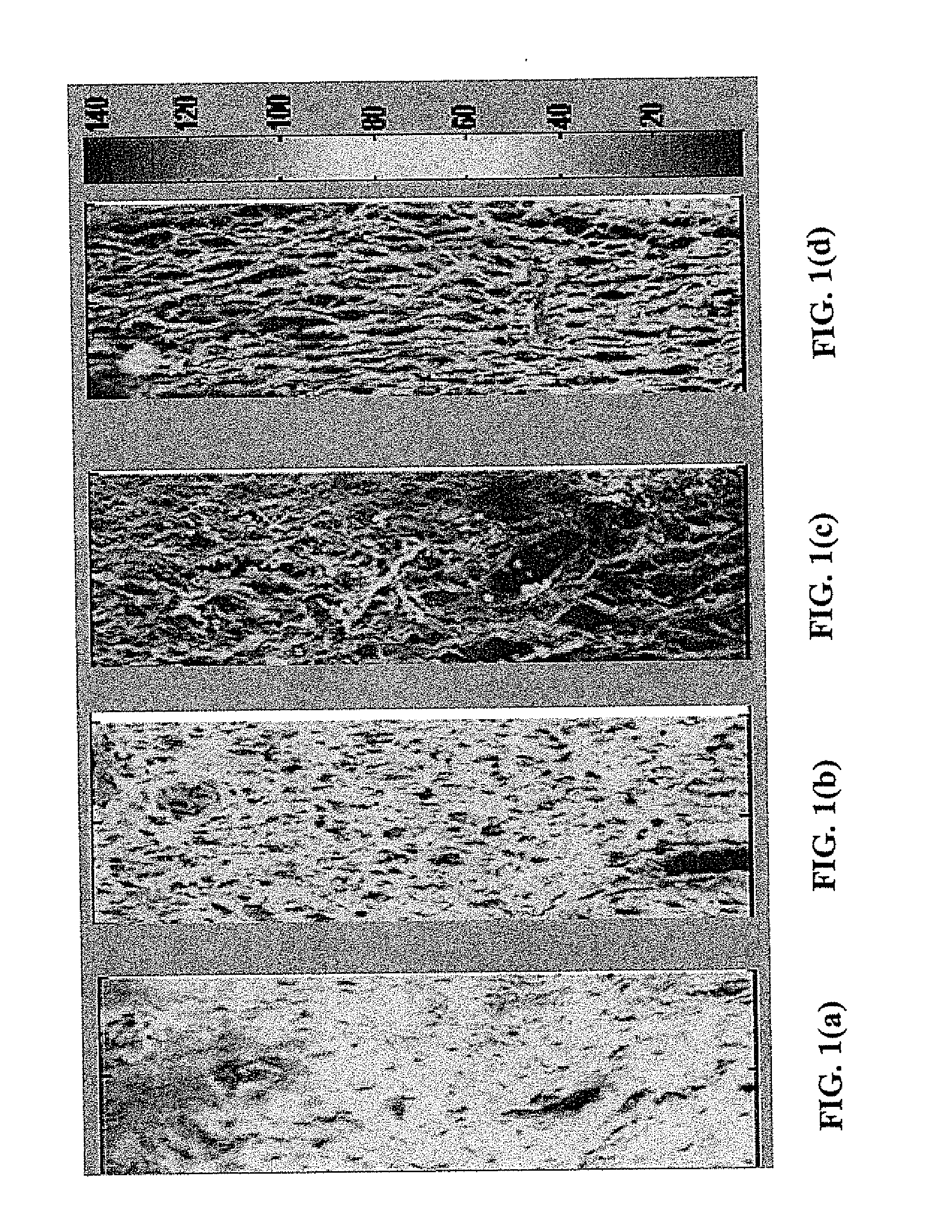
[0022]A set of 5 μm thick tissue sections of human cervix of normal, CIN 1, CIN 2, and CIN 3 tissues stained by H&E is used in this study. The spatial frequencies of these tissues images were measured and analyzed. Their images were taken by a confocal microscope (Leica TCS SPS) and shown in FIGS. 1 (a), (b), (c), and (d) for the normal, CIN 1, 2, and 3 cervical tissues, respectively.

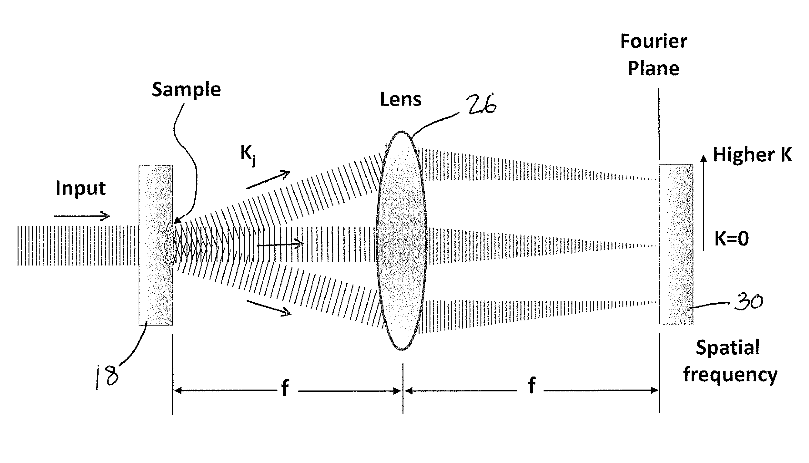
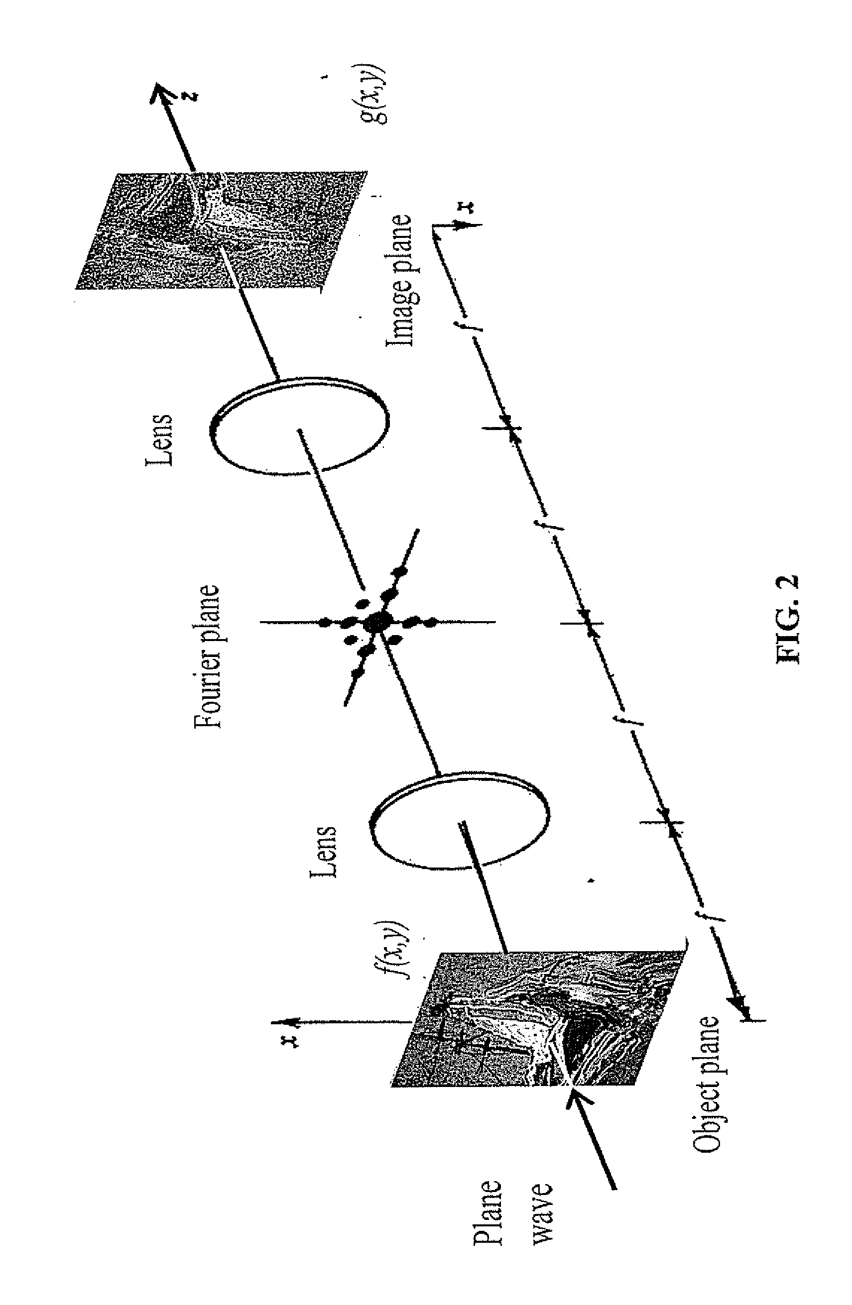
[0023]A 4-F optical system shown in FIGS. 2-2(b) is used to record the Fourier images of the art form. As shown in these Figures, to record the Fourier Transform (FT) of an object, the object is placed at a distance f away from the lens. The image is recorded on a CCD camera at a distance f away from the lens to display the spatial frequency in the FT plane associated with the art form.

[0024]Referring specifically to FIG. 2(a), a spatial frequency spectrometer ...


PUM

PropertyMeasurementUnit
thickaaaaaaaaaa
detecting structureaaaaaaaaaa
spatial frequenciesaaaaaaaaaa

Abstract

Spatial frequency spectra from periodic, aperiodic and quasi-random structures in materials are shown and used to detect differences among objects via internal coding from the spatial frequencies. The method is applied to different grades of human tissues for a new form of histology and pathology, and to detect art forgeries and coding boxes, money and papers and gems. The randomness of material structures on surface and at depths near surface can be detected from the spatial spectrum. In tissue spectral features from normal to different stages of cancer in tissue for ex vivo and in vivo applications can be recognized by different spectral fingerprints content of the spatial frequency. Similarly, the painting for the strokes of artist is different. A new type of instrument is described to analyze materials as a Spatial Frequency Spectrometer.

Description

BACKGROUND OF THE INVENTION[0001]1. Field of the Invention[0002]The invention generally relates to method of and apparatus for obtaining fingerprint information about structures of materials and, more specifically using a spatial frequency spectrometer for and method of detection of spatial structures in materials.[0003]2. Description of the Prior Art[0004]Spatial frequency spectrum may be considered to be able to yield fingerprint information about the surface and internal structures of samples. It can provide spatial information from the periodic, aperiodic, and random structures of the sample from the spatial intensity distribution. A spatial spectrum can be formed given the dominating spatial variation within and on the surface the material. Here, we teach the use of spatial frequency to form a spectrum to obtain information on the internal structure of materials such as tissues-human and animal state, paper goods as money, mail, gems (diamonds defects and quality), and art form...

Claims


Application Information

Patent Timeline
Patent Type & Authority Applications(United States)
IPC IPC(8): G01B9/02G01N21/25
CPCG01B9/02089G01B9/02083A61B5/0059G01N2201/061G01N2201/12G01N21/25G01N21/4788
Inventor ALFANO, ROBERTO R.PU, YANG
Owner ALFANO ROBERT
Why Eureka
Try Eureka