Illumination system and projection device comprising the same

a technology of illumination system and projection device, which is applied in the direction of lighting and heating apparatus, semiconductor devices for light sources, instruments, etc., can solve the problems of large size, increased inability to minimize projectors, so as to reduce the size and weight of illumination system, simplify the entire illumination system, and reduce the effect of light loss

Active Publication Date: 2015-06-25
DELTA ELECTRONICS INC
View PDF5 Cites 24 Cited by
  • Summary
  • Abstract
  • Description
  • Claims
  • Application Information

AI Technical Summary

Benefits of technology

[0034]As mentioned above, the invention configures the light splitting module and the light consolidating module, which can cooperate to reduce the light loss. Besides, the light consolidating module can transmit and receive the light beams, so that the light paths can be centralized within a specific space. This configuration can further simplify the entire illumination system so as to reduce the size and weight of the illumination system. In addition, the illumination system further includes the waveband converting module, so that it can provide better gamut and saturation.

Problems solved by technology

Thus, many optical components are necessary, and unfortunately, the weight of the illumination system is consequentially increased.
Therefore, this design of illumination system, which usually has larger size, is not suitable for the minimization of the projectors.

Method used


Image

  • Illumination system and projection device comprising the same
  • Illumination system and projection device comprising the same
  • Illumination system and projection device comprising the same

Examples


first embodiment

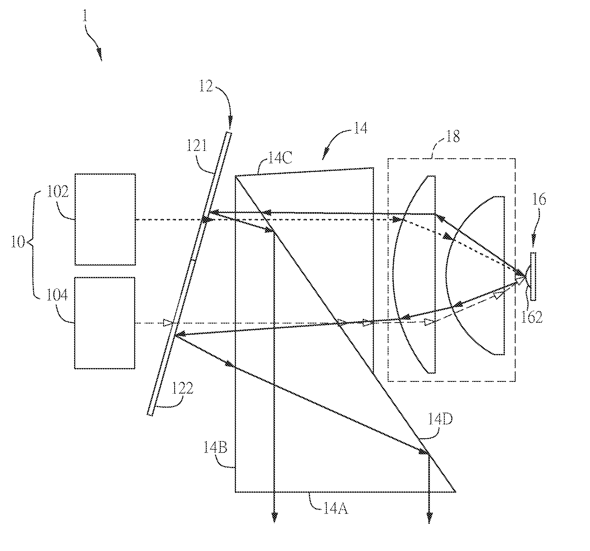
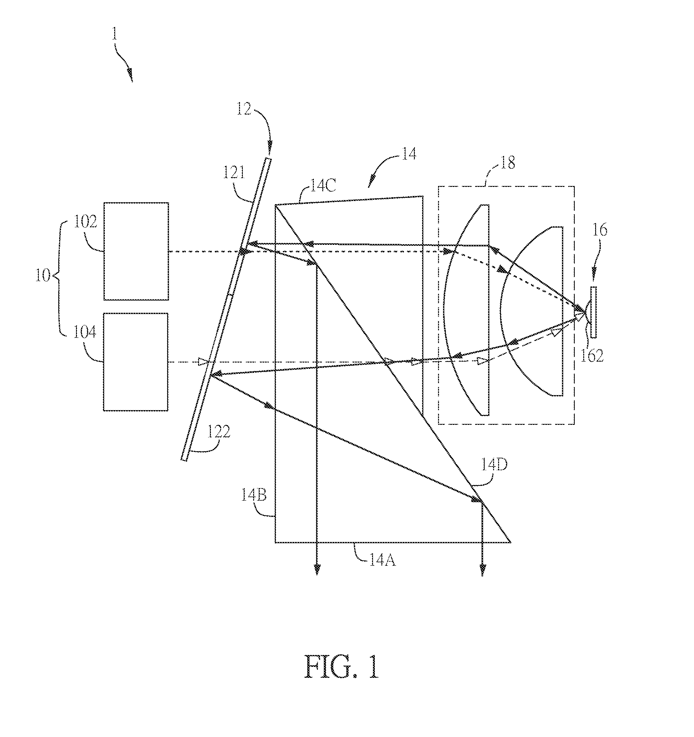
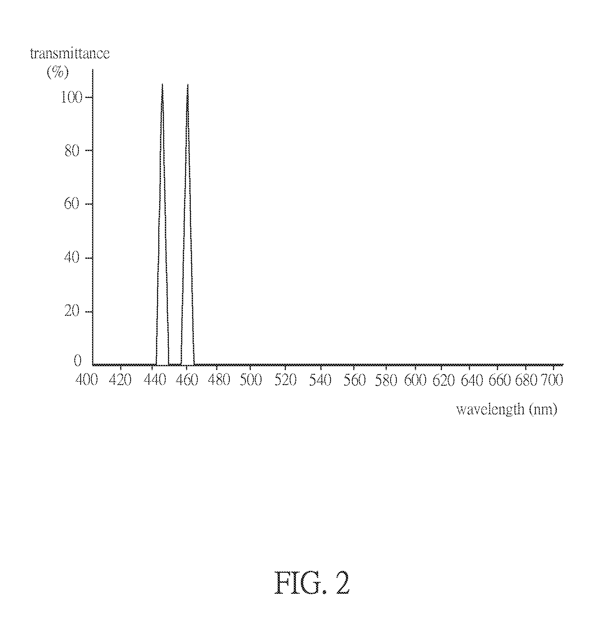
[0052]FIG. 1 is a schematic diagram showing an illumination system according to the invention, FIG. 2 is a schematic diagram showing the wavelength and transmittance of the embodiment of FIG. 1, and FIG. 3 is a schematic diagram showing the wavelength and transmittance of the light beam of the third waveband of FIG. 2, which has traveled through a dichroic element.

[0053]The illumination system 1 of this embodiment includes a light source module 10, a light splitting module 12, a light consolidating module 14 and a waveband converting module 16.

[0054]The light source module 10 includes a first light source 102 for providing a first light beam of a first waveband. Moreover, the light source module 10 may further include a second light source 104, if necessary, for providing a second light beam of a second waveband. The light sources described herein can provide multiple light beams. For example, the first light source 102 can provide multiple first light beams of the first waveband. I...

second embodiment

[0084]Different from the previous embodiment, the light source module 10 of the second embodiment further includes a third light source 106, and the light splitting module 12 further includes a third light splitting element 123.

[0085]In this embodiment, the third light source 106 is disposed at the second light input surface 14C of the light consolidating module 14, while the third light splitting element 123 is disposed between the waveband converting module 16 and the light consolidating module 14.

[0086]In more detailed, the third light source 106 of this embodiment provides a third light beam of a fourth waveband. Herein, the third light beam of the fourth waveband is a red light.

[0087]The third light splitting element 123 of the light splitting module 12 can reflect the light beam of the fourth waveband. In other words, the first light beam of the first waveband (blue light), the second light beam of the second waveband (blue light), the first light beam of the third waveband (y...

third embodiment

[0091]FIGS. 6A and 6B are schematic diagrams showing an illumination system according to the invention, and FIG. 7 is a schematic diagram showing the wavelength and transmittance of the light beam of the third waveband of FIGS. 6A and 6B, which has traveled through a dichroic element.

[0092]The waveband converting module 16a of the third embodiment further includes a second waveband converting zone 162b. Herein, the first waveband converting zone 162a is coated with a green fluorescent material, and the second waveband converting zone 162b is coated with a red fluorescent material.

[0093]The light splitting module 12 of the third embodiment may further include a fourth light splitting element 124 and a fifth light splitting element 125. Each of the fourth light splitting element 124 and the fifth light splitting element 125 can be a dichroic mirror.

[0094]The fourth light splitting element 124 allows the light beam of the second waveband to pass through, and reflects the light beam of ...


PUM


Abstract

An illumination system includes a light source module, a light splitting module, a light consolidating module and a waveband converting module. The light source module has a first light source, which provides a first light beam of first waveband. The light splitting module has a first light splitting element and a second light splitting element. The first light splitting element allows the light beam of first waveband to pass through and reflects the light beam of second waveband. The second light splitting element allows the light beam of second waveband to pass through and reflects the light beam of first waveband. The light consolidating module reflects the light beam having an incident angle greater than a predetermined angel and allows the light beam having an incident angle smaller than the predetermined angel to pass through. The waveband converting module has a first waveband converting zone.

Description

CROSS REFERENCE TO RELATED APPLICATIONS[0001]This Non-provisional application claims priority under 35 U.S.C. §119(a) on Patent Application No(s). 102147876 filed in Taiwan, Republic of China on Dec. 24, 2013, the entire contents of which are hereby incorporated by reference.BACKGROUND OF THE INVENTION[0002]1. Field of Invention[0003]The present invention relates to an illumination system and, in particular, to an illumination system applied to a projection device.[0004]2. Related Art[0005]Recently, the small and compact projection device has become one of the popular products and is the trend of the development in the projector technology. The projection device can be roughly cut into an illumination system and an imaging system. Most manufacturers have their unique designs in the illumination system and imaging system so as to minimize the size of the illumination or imaging system, enhance the performance of the projection device, and provide high-quality images.[0006]The convent...

Claims


Application Information

Patent Timeline
Patent Type & Authority Applications(United States)
IPC IPC(8): G03B21/14F21K99/00
CPCG03B21/142F21Y2101/02F21K9/56F21Y2101/00F21K9/64G03B21/2013G03B21/204
Inventor HUANG, JUNE-JEI
Owner DELTA ELECTRONICS INC
Why Eureka
Try Eureka