
Solenoid drive device

a solenoid drive and drive device technology, applied in the direction of valve operating means/releasing devices, magnets, magnetic bodies, etc., can solve the problems of less stable magnetic performance, difficult to accurately manage the range of alloys, high manufacturing costs, etc., to reduce the enlarged portion sectional area, increase the proportion of components in the opposite biasing direction to the force applied to the plunger, and increase the force of the core attracted to the plunger

Active Publication Date: 2015-06-25
AISIN AW CO LTD
View PDF13 Cites 10 Cited by
  • Summary
  • Abstract
  • Description
  • Claims
  • Application Information

AI Technical Summary

Benefits of technology

The patent describes a design for a magnetic solenoid drive device that includes a core and a plunger. The design includes an increased diameter portion in the core where a recessed portion is located. The recessed portion narrows the path of magnetic flux, which reduces the force in a perpendicular direction and increases the force in the axial direction, resulting in a stronger attraction force for the plunger. This design also sets an imaginary boundary plane to improve the force and positioning of the increased diameter portion. The configuration allows for a cost-effective and efficient solenoid drive device with high magnetic performance.

Problems solved by technology

However, manufacturing cost is high because three parts are combined.
However, it is not easy to accurately manage the range of alloys that are produced by laser beam radiation, the content of the austenite producing element, etc., and magnetic performance is less stable than the structure of Patent Document 2.

Method used


Image

  • Solenoid drive device
  • Solenoid drive device
  • Solenoid drive device

Examples


first embodiment

1. First Embodiment

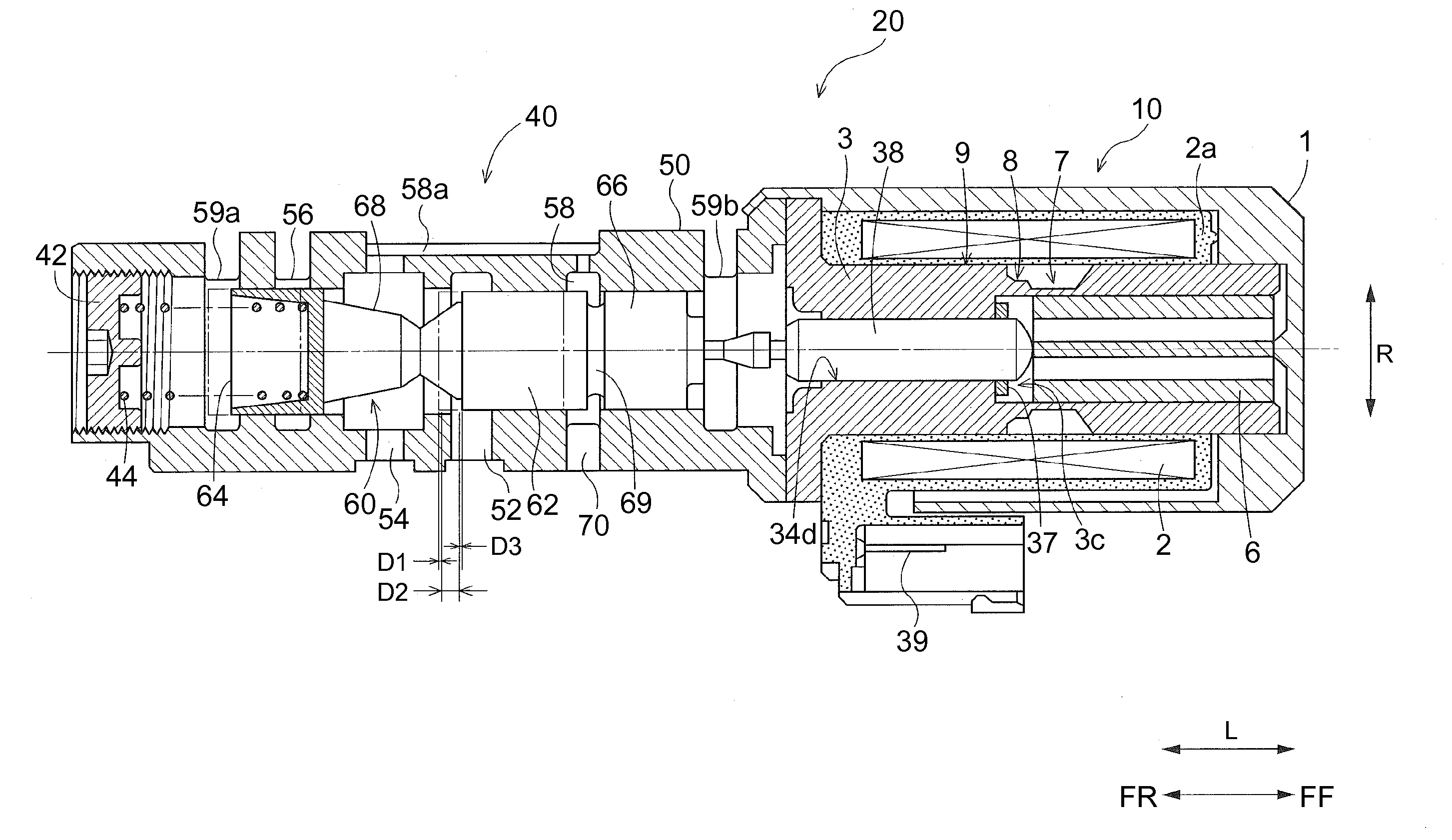
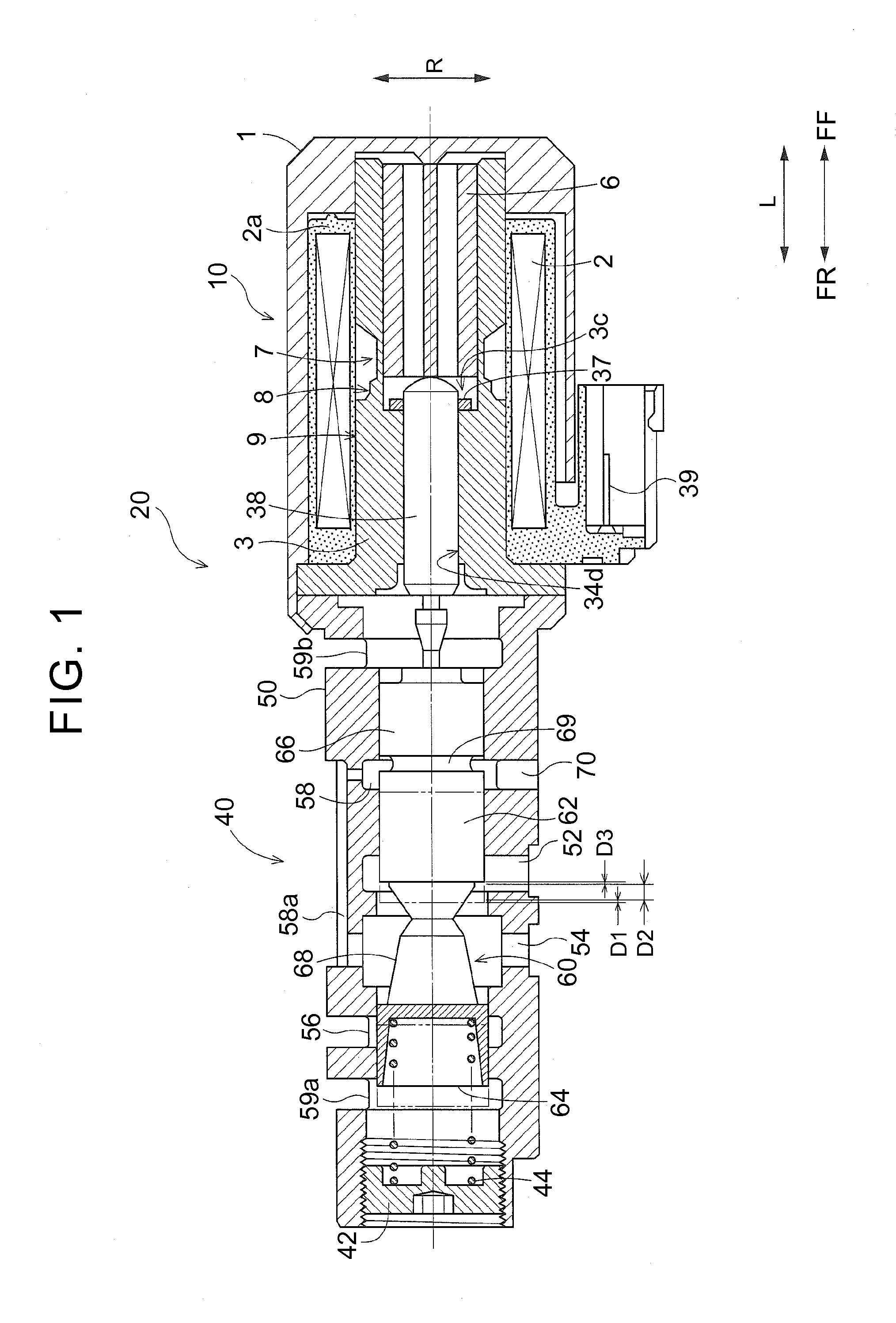
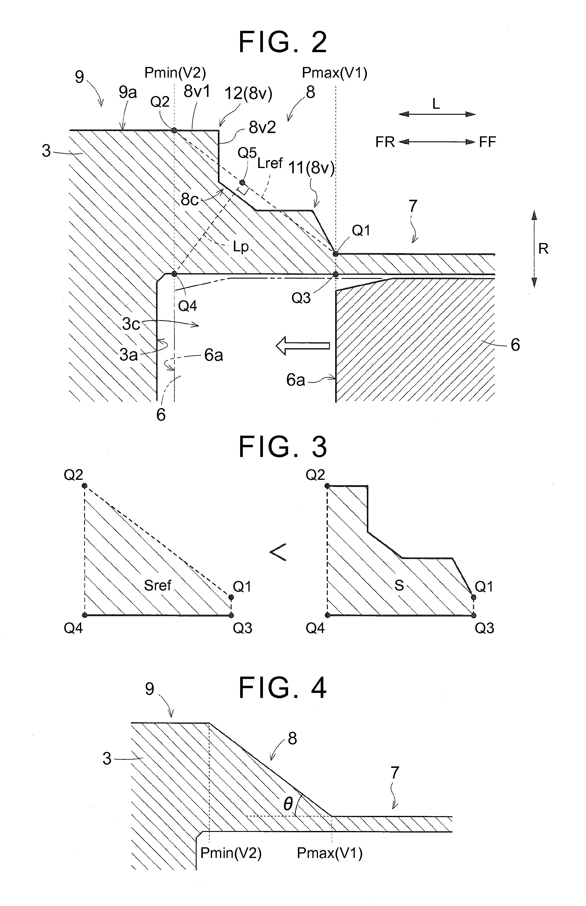
[0042]A first embodiment of the present invention will be described based on the accompanying drawings by using an example in which a solenoid drive device of the present invention is applied to an electromagnetic valve. FIG. 1 is an axial sectional view of an electromagnetic valve 20 including a solenoid drive device 10, and FIG. 2 is a partial enlarged view of a part at or near an increased diameter portion denoted by reference numeral “8” in FIG. 1 and described below. The electromagnetic valve 20 shown in section in FIG. 1 is configured as, e.g., a linear solenoid valve that is used for hydraulic control of a clutch or brake incorporated in an automatic transmission. As shown in FIG. 1, the electromagnetic valve 20 includes the solenoid drive device 10, and a pressure regulating valve portion 40 that is driven by the solenoid drive device 10 to regulate a received oil pressure and output the regulated oil pressure. In the present embodiment, this pressure regu...

second embodiment

2. Second Embodiment

[0067]A second embodiment of the present invention will be described below based on the accompanying drawings. The present embodiment is different from the first embodiment in the specific configuration of the increased diameter portion 8 provided in the core 3. FIG. 8 is a partial enlarged view of a part at or near the increased diameter portion 8 in the present embodiment. Differences from the first embodiment will be mainly described below. The present embodiment is similar to the first embodiment unless otherwise specified.

[0068]The overall configuration of the electromagnetic valve 20 including such a solenoid drive device 10 as shown in FIG. 1 is similar to the first embodiment except for the specific configuration of the increased diameter portion 8. The configuration of the pressure regulating valve portion 40 as the oil pressure control valve is also similar to the first embodiment. Although not specifically described in the first embodiment, as shown in...


PUM


Abstract

An inexpensive solenoid drive device with high magnetic performance is implemented in which a portion accommodating a plunger and a portion attracting the plunger are integrated with a core as a ferromagnetic body. A core includes a magnetic flux limiting portion that is located in a region on the biasing direction side of a first imaginary boundary plane and that is formed so as to have a small thickness in a radial direction, and an increased diameter portion that is formed so that its thickness the radial direction is increased in a continuous or stepwise manner from the first imaginary boundary plane toward the opposite biasing direction side. The increased diameter portion has a recessed portion whose outer surface is recessed toward a radial inner surface with respect to a predetermined increased diameter reference line in axial section of the core.

Description

TECHNICAL FIELD[0001]The present invention relates to solenoid drive devices including a cylindrical coil, a core placed radially inward of the cylindrical coil and having a bottomed cylindrical inner surface, and a plunger placed radially inward of the core such that the plunger can be displaced along the axial direction of the core according to the amount of current that is applied to the cylindrical coil.BACKGROUND ART[0002]An electromagnetic valve using such a solenoid drive device is disclosed in Japanese Patent Application Publication No. H11-287348 (JP H11-287348 A) (Patent Document 1). This electromagnetic valve includes a cylindrical coil (solenoid), a plunger that is capable of moving in the axial direction by current application to the solenoid, and a core as a magnetic body that attracts the plunger according to excitation of the solenoid. A yoke as a magnetic body having a cylindrical portion is provided radially inward of the solenoid. The core has an accommodating por...

Claims


Application Information

Patent Timeline
IPC IPC(8): H01F3/00
CPCH01F3/00H01F7/081H01F7/1607F16K31/0613F16K31/0675H01F7/13H01F2007/085H01F7/16
Inventor IRIE, KEIICHIROTANAKA, TOMOYUKI
Owner AISIN AW CO LTD
Learn More