
Common fabrication of different semiconductor devices with different threshold voltages

a technology of semiconductor devices and threshold voltages, applied in the field of semiconductor devices, can solve the problems of cost prohibitive use of a separate mask for each desired threshold voltage, and the non-uniform distribution of the resultant threshold voltages

Inactive Publication Date: 2015-06-25
GLOBALFOUNDRIES INC
View PDF2 Cites 282 Cited by
  • Summary
  • Abstract
  • Description
  • Claims
  • Application Information

AI Technical Summary

Benefits of technology

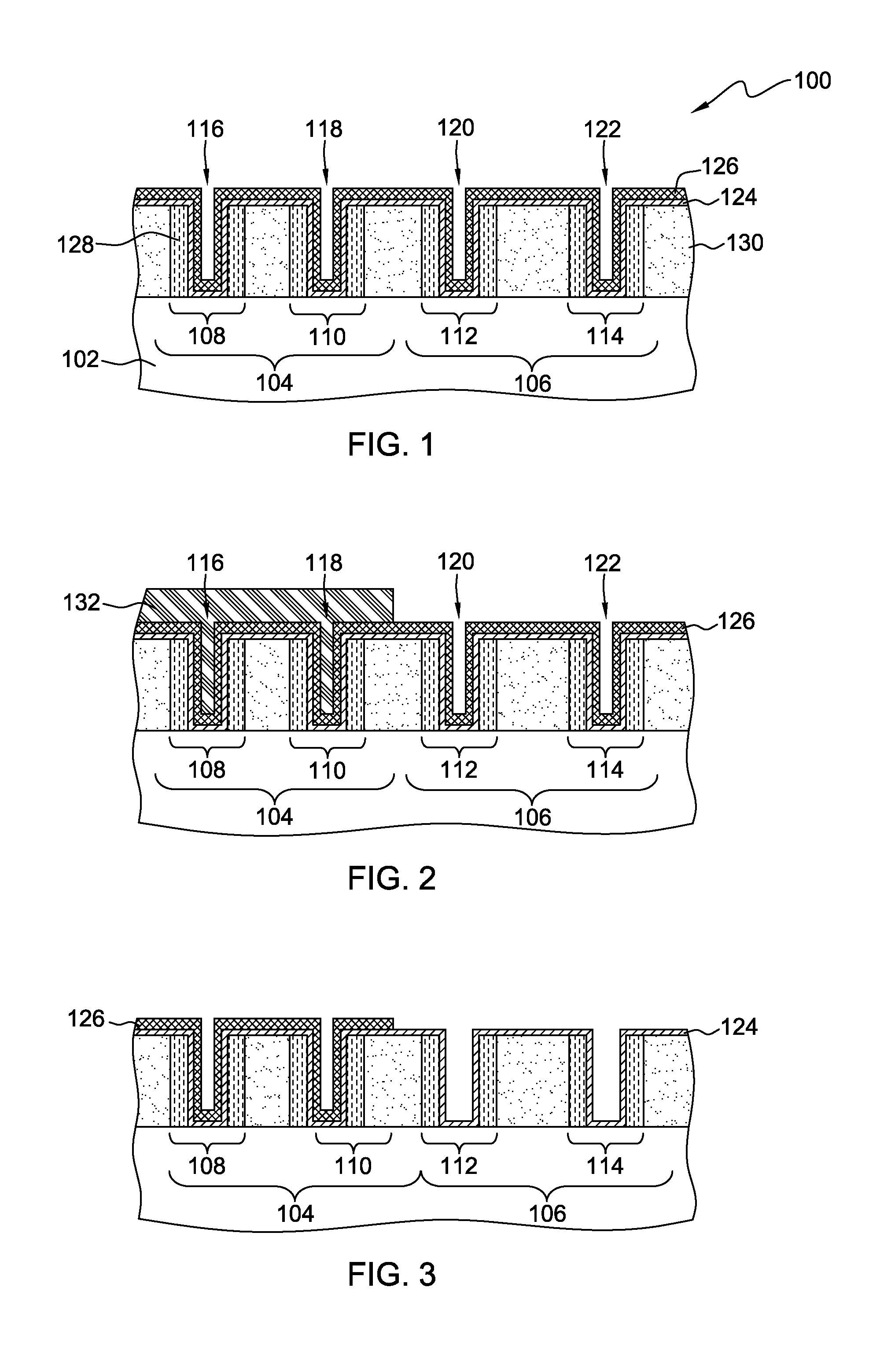
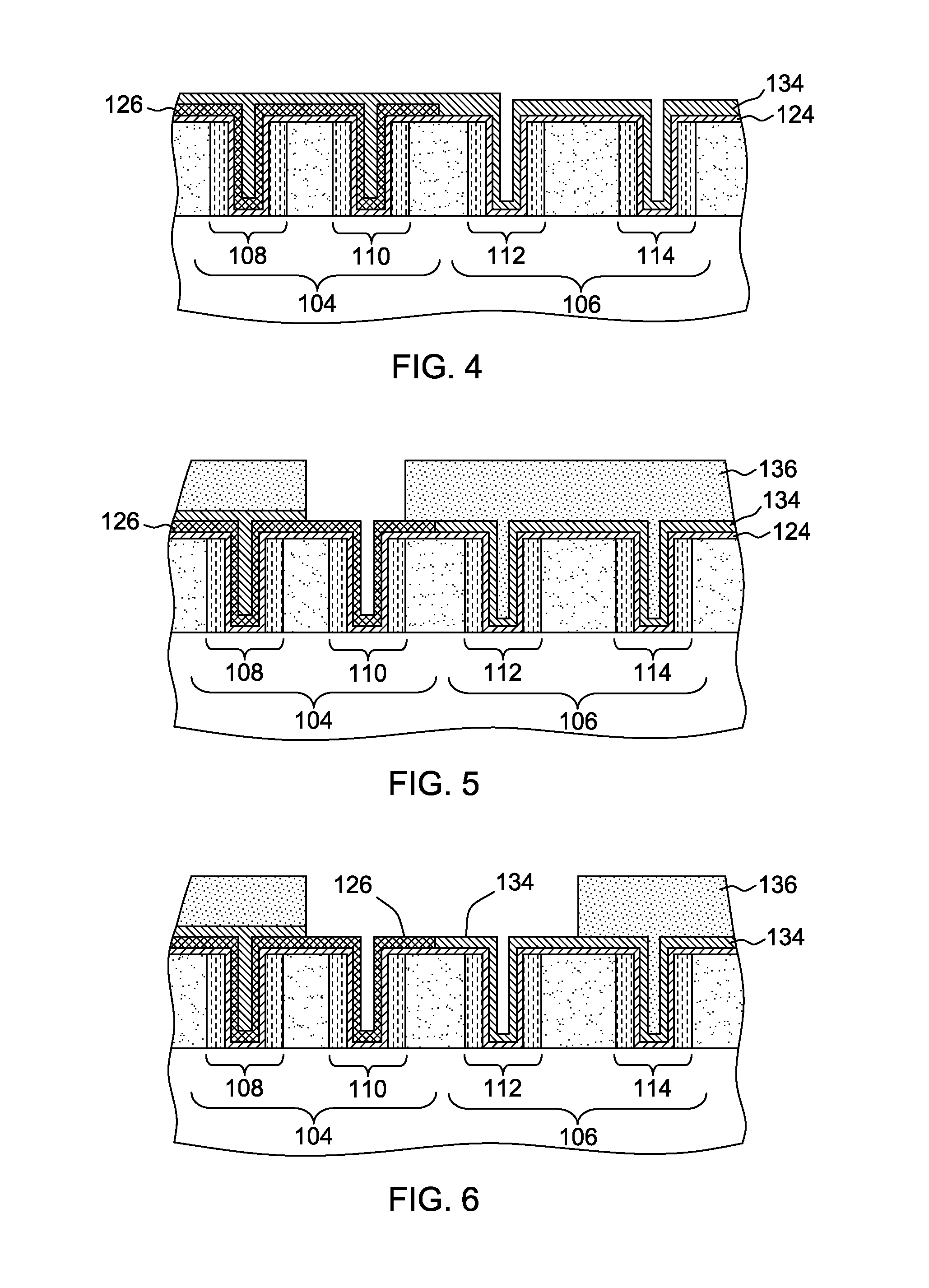
The patent text describes a method and structure for creating semiconductor devices with different threshold voltages. The method involves using a dielectric layer and a blanket layer of a work function material to achieve desired work functions for the semiconductor devices. The work function material is chosen to provide different work functions for the semiconductor devices, while also protecting them and adding impurities to achieve the desired work function. The patent also describes a combination semiconductor device that includes a semiconductor substrate with both n-type and p-type semiconductor devices covered by a blanket layer of a dielectric material, and at least one layer of work function material over each device type. The work function materials are chosen to provide different work functions and can include impurities. The technical effects of this patent include the ability to create semiconductor devices with different threshold voltages and work functions using a single semiconductor structure.

Problems solved by technology

However, the traditional techniques typically employed to manipulate the threshold voltage in such devices, result in non-uniform distribution of the resultant threshold voltages as well as using separate masks for each desired threshold voltage.
While the non-uniformity of the resultant threshold voltages can cause mobility degradation and junction leakage current, using a separate mask for each desired threshold voltage may be cost prohibitive, more particularly so, as the semiconductor device fabrication processing continues to decrease to smaller dimensions.

Method used


Image

  • Common fabrication of different semiconductor devices with different threshold voltages
  • Common fabrication of different semiconductor devices with different threshold voltages
  • Common fabrication of different semiconductor devices with different threshold voltages

Examples


Embodiment Construction

[0025]Aspects of the present invention and certain features, advantages, and details thereof, are explained more fully below with reference to the non-limiting examples illustrated in the accompanying drawings. Descriptions of well-known materials, fabrication tools, processing techniques, etc., are omitted so as not to unnecessarily obscure the invention in detail. It should be understood, however, that the detailed description and the specific examples, while indicating aspects of the invention, are given by way of illustration only, and are not by way of limitation. Various substitutions, modifications, additions, and / or arrangements, within the spirit and / or scope of the underlying inventive concepts will be apparent to those skilled in the art from this disclosure.

[0026]Approximating language, as used herein throughout the specification and claims, may be applied to modify any quantitative representation that could permissibly vary without resulting in a change in the basic fun...


PUM

PropertyMeasurementUnit
dielectric constantaaaaaaaaaa
thicknessaaaaaaaaaa
thicknessaaaaaaaaaa

Abstract

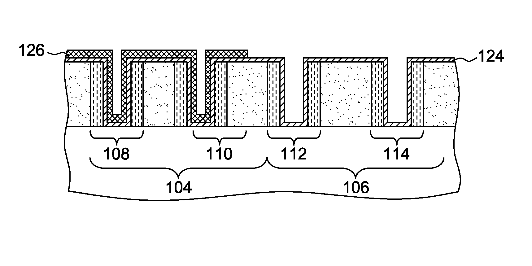
A multi-device semiconductor structure including a p-type logic device, a p-type memory device, a n-type logic device and a n-type memory device are provided on a bulk silicon substrate. Each of these devices includes a dielectric layer and either a n-type or a p-type work function layer disposed over the dielectric layer. Some of the various device types of the multi-device semiconductor structure are protected, and impurities, such as aluminum and / or nitrogen, are added to the exposed work function layers to achieve one or more other desired work functions with different threshold voltages.

Description

BACKGROUND OF THE INVENTION[0001]1. Technical Field[0002]The present invention generally relates to semiconductor devices and methods of fabricating the semiconductor devices, more particularly, to providing different threshold voltages for different semiconductor devices being fabricated together.[0003]2. Background Information[0004]As is known, semiconductor devices, such as integrated circuit devices typically include a large number of transistors, logic devices and other types of devices within a single chip or wafer area. Each of these several different devices may have different corresponding threshold voltages (i.e., operating voltage or turn-on voltage) within the single chip or wafer area, to optimize performance or power. For example, an integrated circuit device may include a low threshold voltage device and a high threshold voltage device. Each of these different devices with different corresponding threshold voltages may be achieved either by doping the channel area usi...

Claims


Application Information

Patent Timeline
Patent Type & Authority Applications(United States)
IPC IPC(8): H01L27/088H01L21/28H01L21/265H01L21/223H01L21/8234H01L29/51
CPCH01L27/088H01L21/823412H01L29/517H01L21/823462H01L21/2236H01L21/28158H01L21/265H01L21/823842H01L21/823857H01L27/092H01L21/28079H01L21/28088H01L29/66545
Inventor KIM, HOONCHOI, KISIKLEE, JAE YOUNG
Owner GLOBALFOUNDRIES INC
Learn More