

Trimming method for patch antenna and patch antenna structure
- Summary
- Abstract
- Description
- Claims
- Application Information
AI Technical Summary
Benefits of technology
Problems solved by technology
Method used
Image

Examples
Embodiment Construction
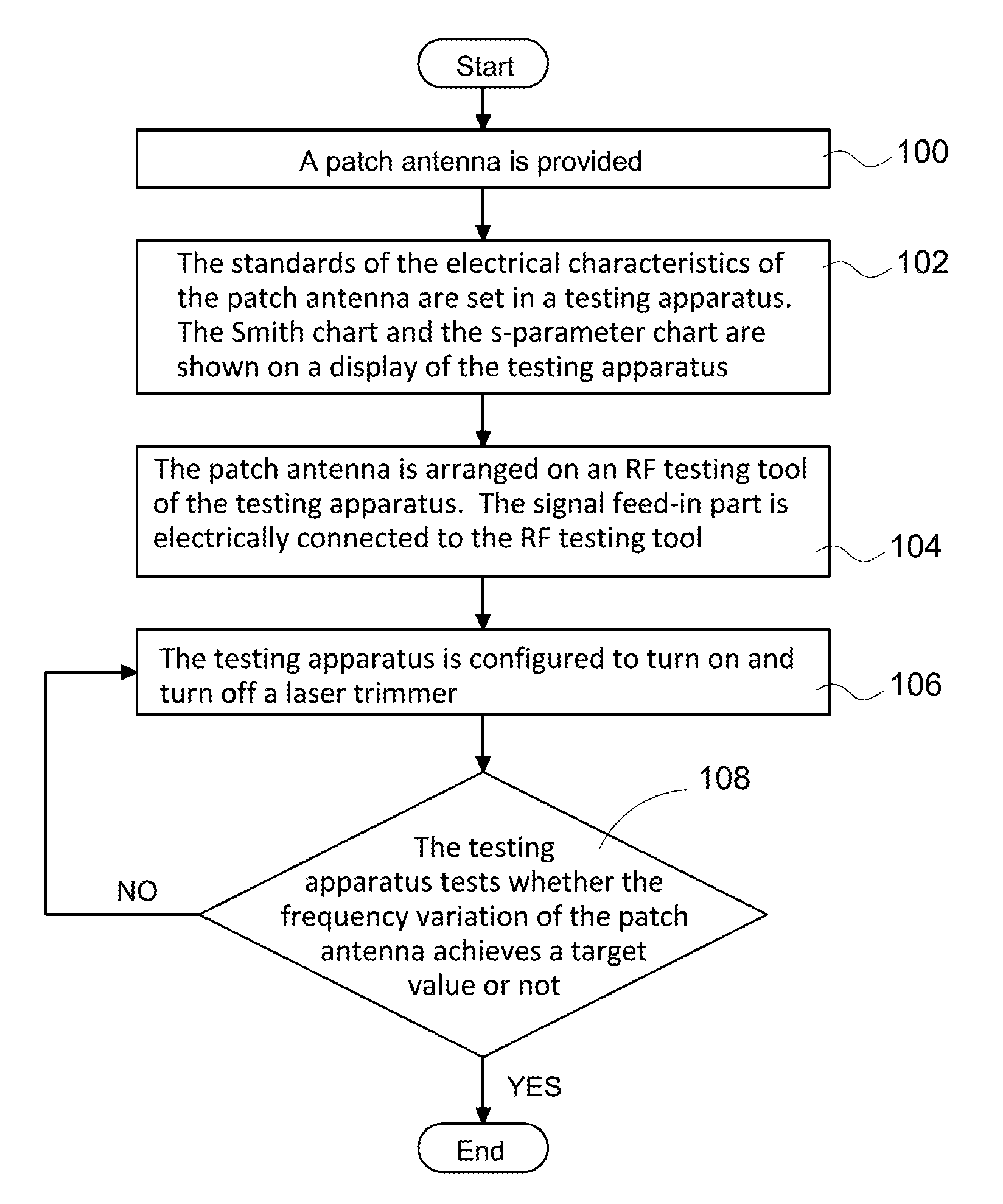
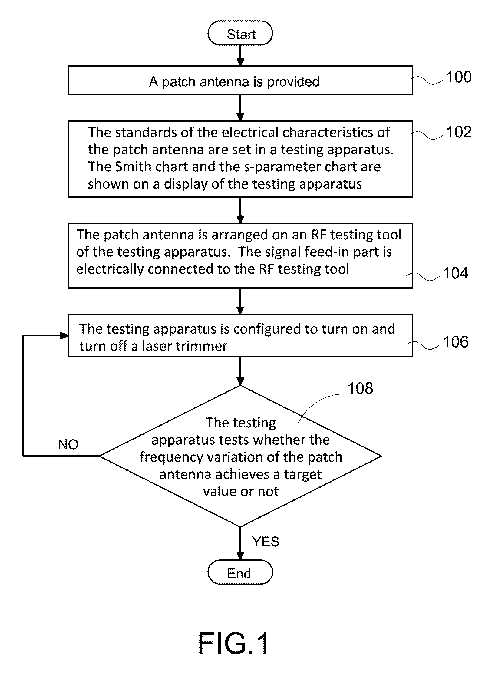
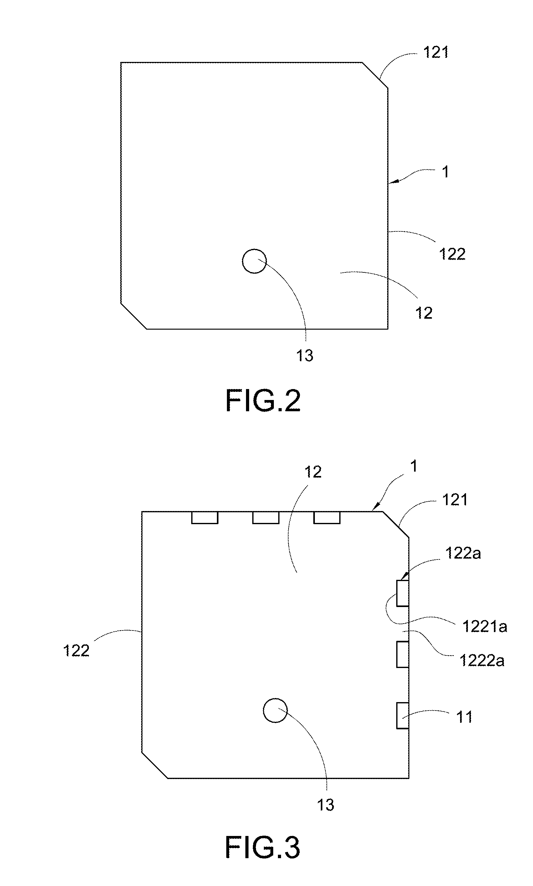
[0021]FIG. 1 shows a flow chart of a trimming method for a patch antenna of the present invention. FIG. 2 shows a schematic diagram showing the radiation metal surface of the patch antenna has not been cut. FIG. 3 shows a schematic diagram showing the radiation metal surface of the patch antenna includes two dashed edges. FIG. 4 shows a schematic diagram showing the radiation metal surface of the patch antenna includes four dashed edges. The trimming method for a patch antenna of the present invention includes following steps. A patch antenna 1 is provided (step 100). The patch antenna 1 includes an underlying carrier 11. A radiation metal surface 12 is arranged on a top side of the underlying carrier 11. The radiation metal surface 12 includes two bevel edges 121 opposite to each other along a diagonal line and four straight edges 122. Moreover, a signal feed-in part 13 which is arranged on the underlying carrier 11 and is in columnar shape is electrically connected to the radiatio...
PUM
| Property | Measurement | Unit |
|---|---|---|
| Depth | aaaaa | aaaaa |
| Frequency | aaaaa | aaaaa |
Abstract
Description
Claims
Application Information