

Motor controller
a technology of motor controller and control panel, which is applied in the direction of electronic commutation motor control, motor/generator/converter stopper, dynamo-electric converter control, etc., can solve the problems of increasing torque ripple, reduce or prevent torque ripple, and reduce reference flux
- Summary
- Abstract
- Description
- Claims
- Application Information
AI Technical Summary
Benefits of technology
Problems solved by technology
Method used
Image

Examples
Embodiment Construction
[0055]ψ hereinafter referred to as “psi”.
[0056]θ. hereinafter referred to as “theta”
[0057]ω. hereinafter referred to as “omega”
[0058]⇑ hereinafter referred to as “up-arrow”
[0059]⇓ hereinafter referred to as “down-arrow”
[0060]→ hereinafter referred to as “right-arrow”
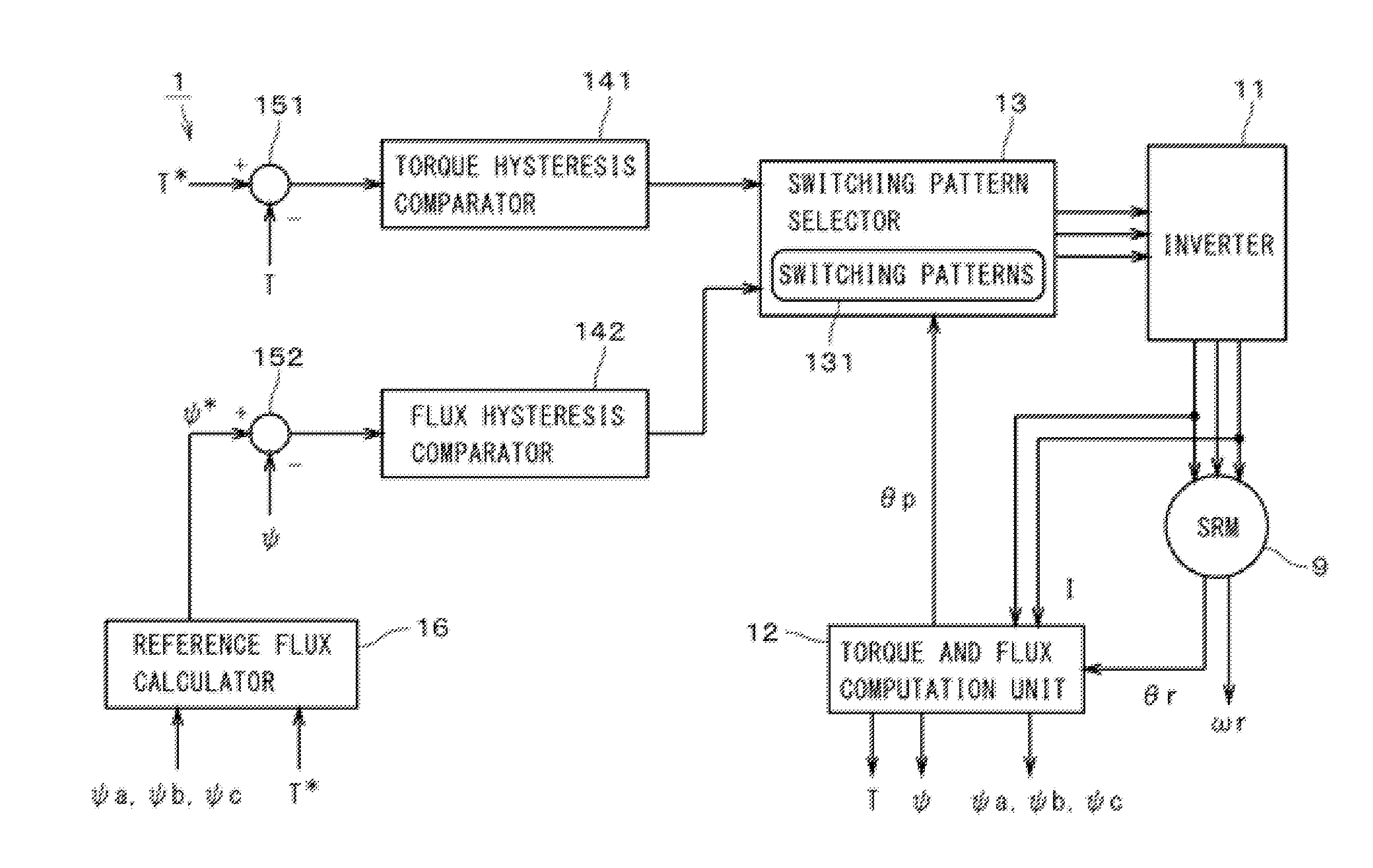
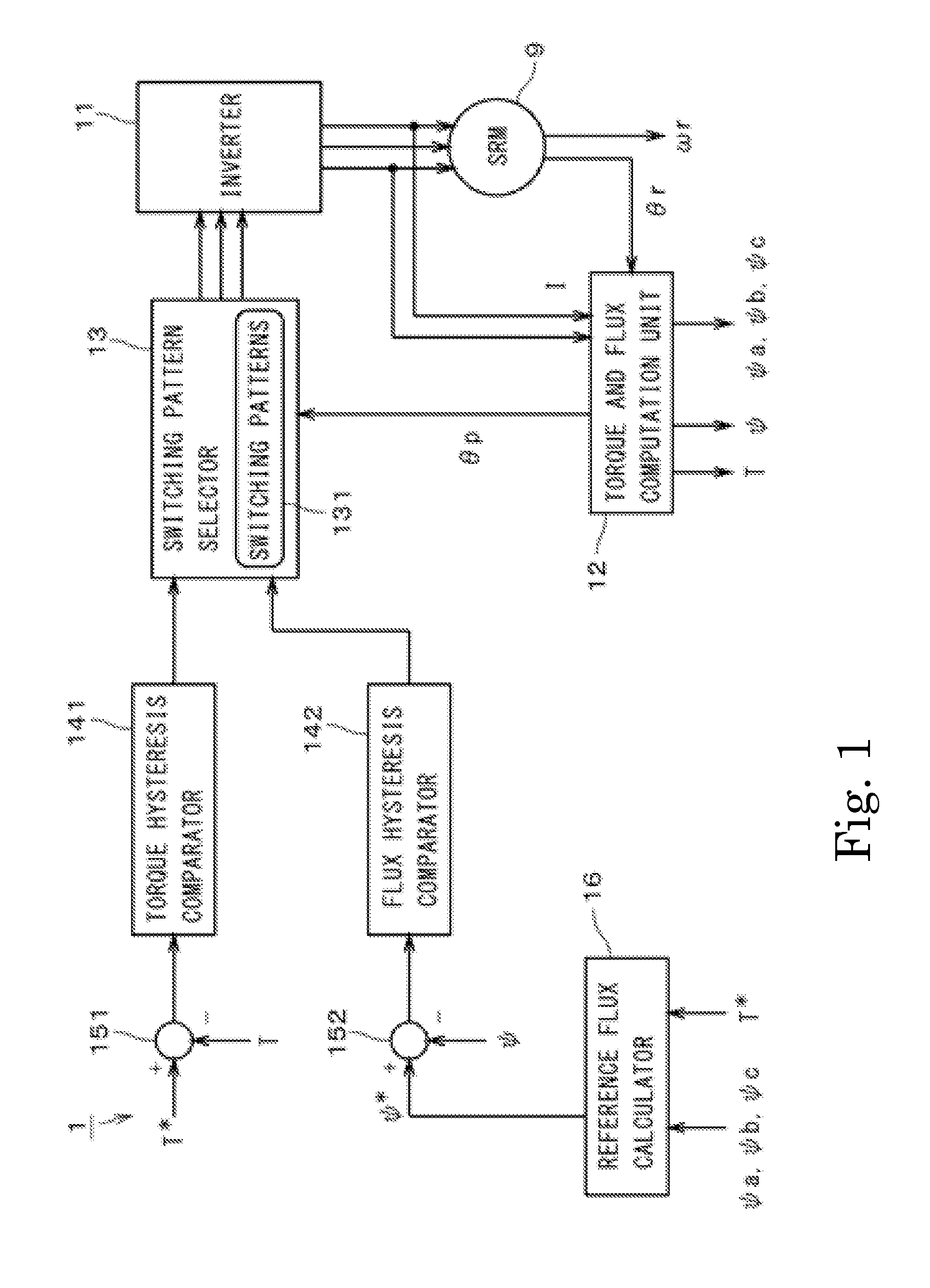
[0061]FIG. 1 is a block diagram showing a motor controller 1. The motor controller 1 is configured to control an SRM (Switched Reluctance Motor) 9, preferably under DTC (Direct Torque Control).
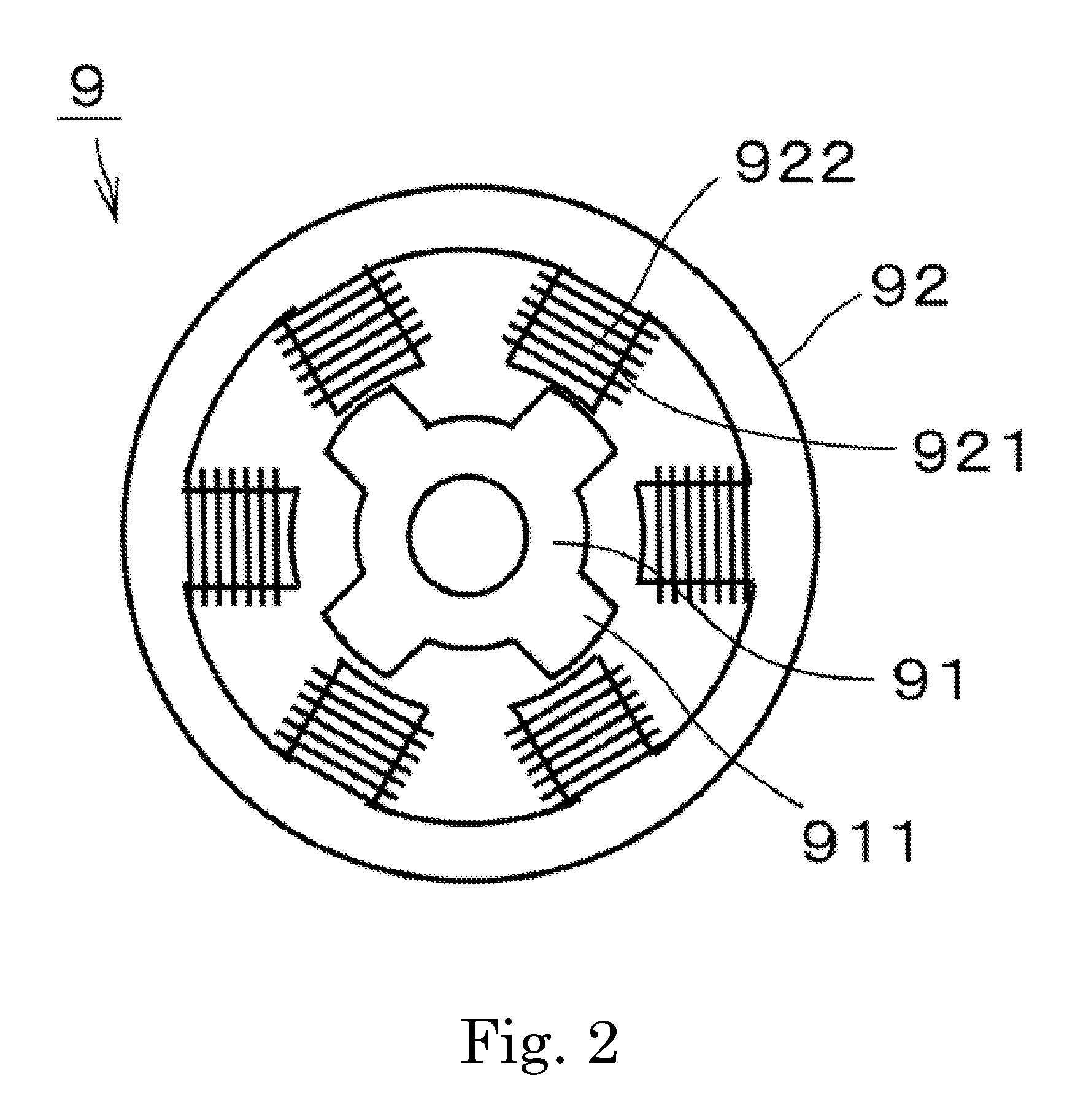
[0062]FIG. 2 is a schematic view of the SRM 9. The SRM 9 preferably includes a rotor 91 and a stator 92. The rotor 91 is rotatably supported around the rotating axis by a bearing mechanism (not shown). The rotor 91 includes a plurality of portions 911 protruding toward the stator 92, and the stator 92 includes a plurality of portions 921 protruding toward the rotor 91, in other words, the SRM 9 preferably has double saliency. A wire is wound around each protruding portion 921 of the stator 92 to define a coil 922. The rotor 91 does...
PUM
 Abstract
Description
Claims
Application Information