
Device for measuring the pressure of a gas in a pollution control or energy storage system

a technology for pollution control or energy storage systems, applied in the direction of material thermal analysis, rapid change measurement, instruments, etc., can solve the problems of high cost and bulkyness of pressure sensors and regulators

Inactive Publication Date: 2015-07-02
INERGY AUTOMOTIVE SYST RES (SA)
View PDF11 Cites 0 Cited by
  • Summary
  • Abstract
  • Description
  • Claims
  • Application Information

AI Technical Summary

Benefits of technology

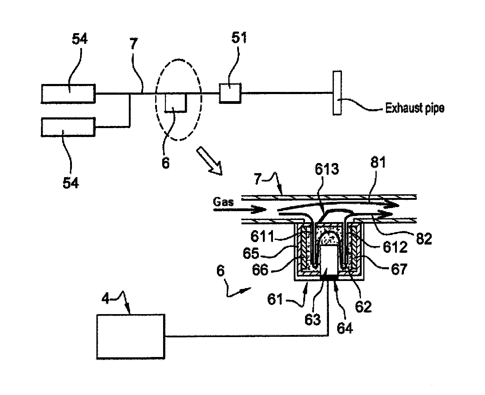
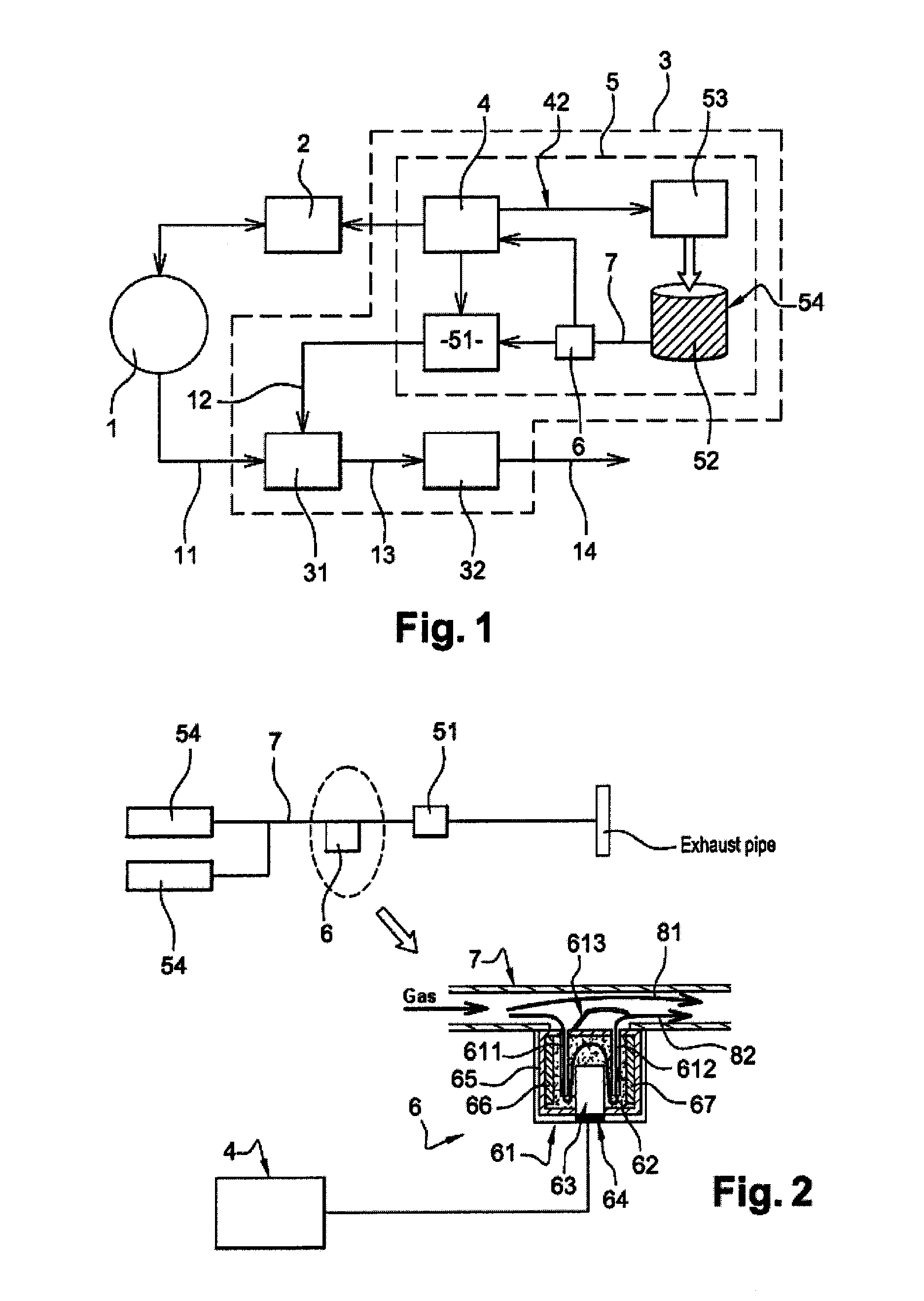
The invention provides a device that can measure gas pressure without using a pressure sensor or regulator. The device is small and easy to assemble and is intended for use in energy storage or pollution control systems for vehicles. The device uses a processing unit that is already present on the vehicle, reducing the cost. The device uses a Clausius-Clapeyron relationship to accurately measure pressure and uses thermal insulation to prevent disturbances in temperature measurement. The device also uses a phase-change material to ensure accurate pressure measurement and has a signature to indicate if the pressure is above or within a given range.

Problems solved by technology

However, these pressure sensors and regulators are expensive and bulky.

Method used


Image

  • Device for measuring the pressure of a gas in a pollution control or energy storage system
  • Device for measuring the pressure of a gas in a pollution control or energy storage system

Examples


Embodiment Construction

[0037]In the remainder of the description, and by way of example, the gas for which it is desired to measure the pressure is a gas intended to be injected into the exhaust line of a vehicle in order to reduce the amount of nitrogen oxides (NOx) in the exhaust gases. By way of example, the gas is considered to be ammonia. Of course, in an embodiment variant, the gas may be of any other type, and in particular hydrogen.

[0038]As illustrated in the example of FIG. 1, the engine 1 of the vehicle is controlled by an electronic control unit 2 (sometimes referred to as ECU or engine control unit). The engine 1 cooperates with an SCR pollution control system 3. On leaving the engine, the exhaust gases 11 are directed toward an ammonia injection module 31, in which the ammonia 12 is mixed with the exhaust gases 11. The ammonia / exhaust gases mixture 13 then passes over an SCR catalyst 32 which enables the reduction of the nitrogen oxides (NOx) by the ammonia. The decontaminated exhaust gases 1...


PUM


Abstract

A device for measuring a pressure of a gas in a pollution control or energy storage system, including: a housing including an inlet and an outlet; a compound disposed inside the housing and configured to absorb at least one portion of gas entering the housing through the inlet, the non-absorbed portion of gas exiting the housing via the outlet; at least one sensor configured to measure a temperature of the compound; a processing unit configured to determine the pressure of the gas by using the temperature measurement from the sensor and a predefined pressure / temperature ratio.

Description

FIELD OF THE INVENTION[0001]The present invention relates to a device for measuring the pressure of a gas.[0002]The invention applies in particular, but not exclusively, to measuring the pressure inside an energy storage system such as, for example, a hydrogen storage reservoir mounted on a motor vehicle.[0003]The invention applies also, but not exclusively, to measuring the pressure of a gas circulating in a pollution control system intended to reduce the amount of nitrogen oxides (NOx) in the exhaust gases of a motor vehicle. In the remainder of this document, every effort will be made to describe, by way of illustrative example, this particular type of application.[0004]Of course, the present invention applies to measuring the pressure of any type of gas that may be present in a pollution control or energy storage system.TECHNOLOGICAL BACKGROUND[0005]The nitrogen oxides present in the exhaust gases of vehicles, in particular diesel vehicles, can be eliminated by a pollution contr...

Claims


Application Information

Patent Timeline
IPC IPC(8): G01L11/00G01N33/00
CPCG01N33/0036G01L11/002G01L23/24G01N33/0054Y02A50/20
Inventor VAN SCHAFTINGEN, JULES-JOSEPHDOUGNIER, FRANCOISMADOUX, DOMINIQUEHABUMUREMYI, JEAN-CLAUDE
Owner INERGY AUTOMOTIVE SYST RES (SA)
Learn More