Local seal for encapsulation of electro-optical element on a flexible substrate

a technology of electro-optical elements and local seals, which is applied in the field of local seals for encapsulation of electro-optical elements on flexible substrates, can solve the problems of limited heat tolerance, limited tolerance of optical elements, so as to achieve low permeation rates and ensure the flexibility of finished light-emitting products

Active Publication Date: 2015-07-02
GLOBAL OLED TECH
View PDF22 Cites 33 Cited by
  • Summary
  • Abstract
  • Description
  • Claims
  • Application Information

AI Technical Summary

Benefits of technology

[0025]In a first aspect, local encapsulation seals are provided under respective individual light-emitting elements. In accordance with preferred embodiments of the present invention, the local encapsulation seals are formed of a glass material. The advantages of glass include low permeation rates for both moisture and oxygen, as well as optical clarity. See, for example, U.S. Pat. No. 7,026,758 to Guenther. These advantages can be retained by forming a local glass seal below each light-emitting element. Because the glass need not be a continuous sheet, flexibility of a finished light-emitting product is not compromised.
[0032]The combination of a thin film encapsulation structure with local seals is mutually beneficial. The local seals provide protection against pixel damage due to pinhole defects in the thin film encapsulation structure, particularly since pixels are most sensitive to pinhole defects directly below or above the pixel. Conversely, the thin film encapsulation structure reduces uptake of moisture or oxygen by areas of internal layers between the pixels. While such uptake of moisture or oxygen may not directly impact performance of a display or lighting product, the moisture or oxygen so absorbed can migrate laterally into the active area of a light-emitting element, where the moisture or oxygen will likely impact product performance. Thus, the thin film encapsulation structure can greatly improve protection of a light-emitting element against secondary paths of moisture or oxygen ingress.
[0034]In an eleventh aspect of the present invention, the local seals may additionally perform a lens function. In some embodiments, a local seal has substantially planar top and bottom surfaces, and performs no lens function. In other embodiments, a local seal has a curved top or bottom surface and acts as a converging lens. A converging lens function is desirable, for example, in a battery-powered personal device, where light emitted in directions away from a user represents wasted energy and reduced battery life. In still other embodiments, a local seal has a curved top or bottom surface and acts as a diverging lens. A diverging lens function is advantageous, for example, in television products, digital signage, and some lighting products, where wide field of view is desirable.
[0035]In a twelfth aspect of the present invention, the local seals may additionally perform a different optical function, such as a filter, a color converter, and / or a scatterer. In some embodiments, the local seal is formed of a glass powder suspension doped with one or more pigments, so as to tailor the emission profile with respect to the natural emission profile of the underlying electroluminescent element. This aspect of the invention is advantageous for display products having a common emissive layer for different color pixels. This aspect of the invention is also advantageous for lighting products to tailor the color temperature of the emitted light. In some embodiments, the glass powder suspension is doped with a fluorescent or other color shifting material. This aspect of the invention is advantageous, for example, in a lighting product, to convert cold bluish light to a warmer color. In some embodiments, the glass powder suspension may be mixed with a powder of a refractory material. When the glass is fused during manufacture of the local seals, the refractory materials remain intact. Thereby the local seals lose some of their optical clarity and take on a scattering function.
[0037]In a fourteenth aspect of the present invention, the deposited glass powder is fused without damaging any overlaid TFT or electroluminescent layers. In some embodiments, fusing of the glass powder can be achieved by bulk heating of the entire product. In other embodiments, fusing of the glass powder can be achieved by uniformly heating a surface of the product on which local seals are being formed. In yet other embodiments, heat is deposited locally so that the areas to be sealed absorb more energy per unit area than areas between seals.

Problems solved by technology

Many of these electro-optical elements contain organic materials and have limited tolerance for heat.
OLED elements are particularly sensitive to moisture, are sensitive to oxygen, and have limited tolerance for heat.
However, as discussed below, encapsulation suitable for flexible products has not been satisfactorily addressed to date, especially for the stringent encapsulation requirements of OLED elements.
A metal substrate is opaque and is only suitable for a bottom-emitting display, while a glass substrate is relatively thick and rigid, and not well-suited for roll-to-roll manufacture or flexible displays.
Thin film encapsulation offers manufacturing benefits, but suffers from the relatively high permeability of polymer materials, and the difficulty of depositing or forming thin film layers that are free of pinholes.
The permeability requirements for OLED are stringent and limit the choice of suitable materials.
But, the use of laminated layers requires additional process steps, with attendant costs.
This encapsulant is pre-formed, which entails additional manufacturing equipment and cost, and also requires careful alignment between the pre-formed optical structures on the encapsulant and a pixel pattern on an underlying display substrate.

Method used


Image

  • Local seal for encapsulation of electro-optical element on a flexible substrate
  • Local seal for encapsulation of electro-optical element on a flexible substrate
  • Local seal for encapsulation of electro-optical element on a flexible substrate

Examples


first embodiment

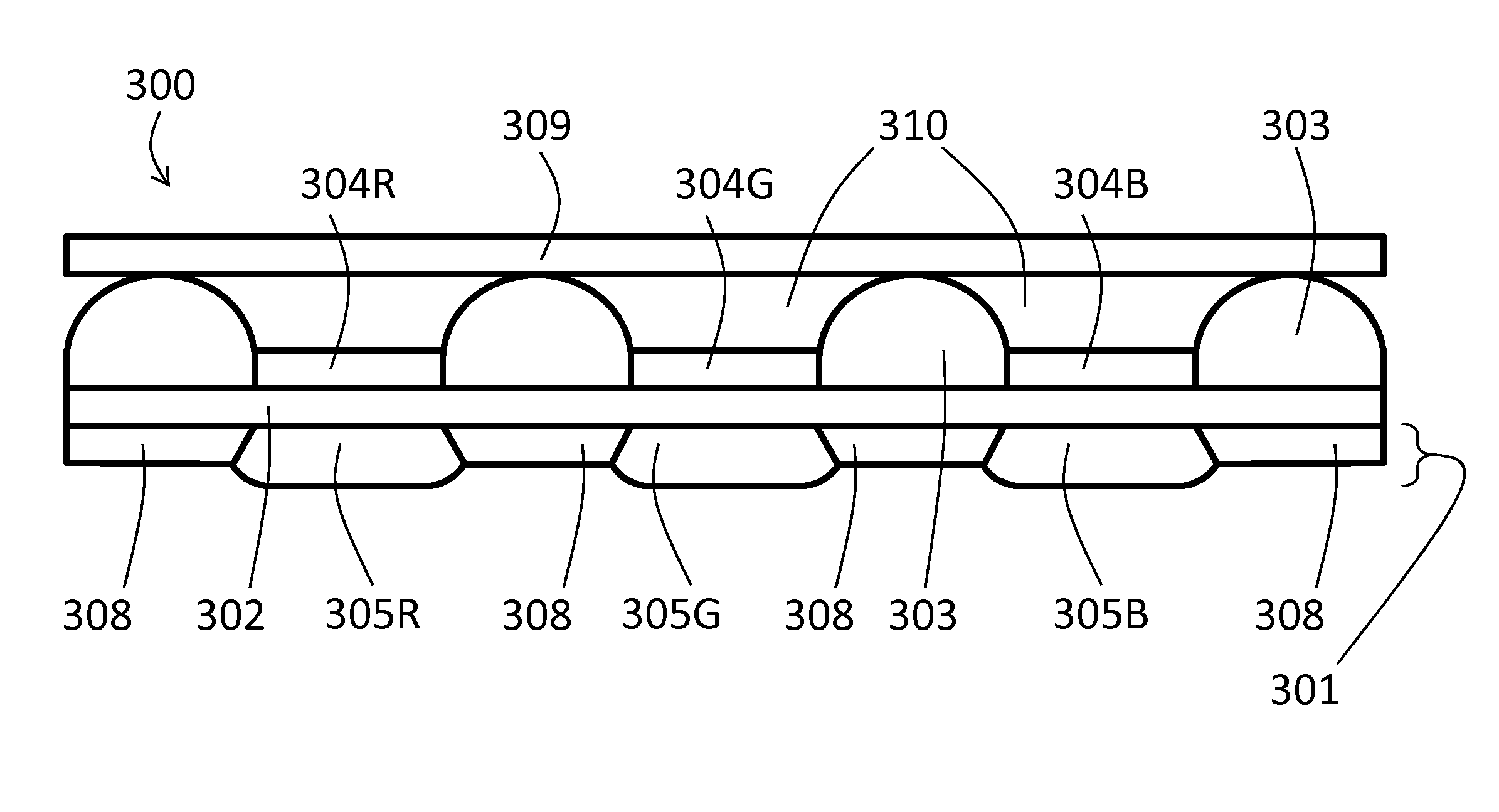
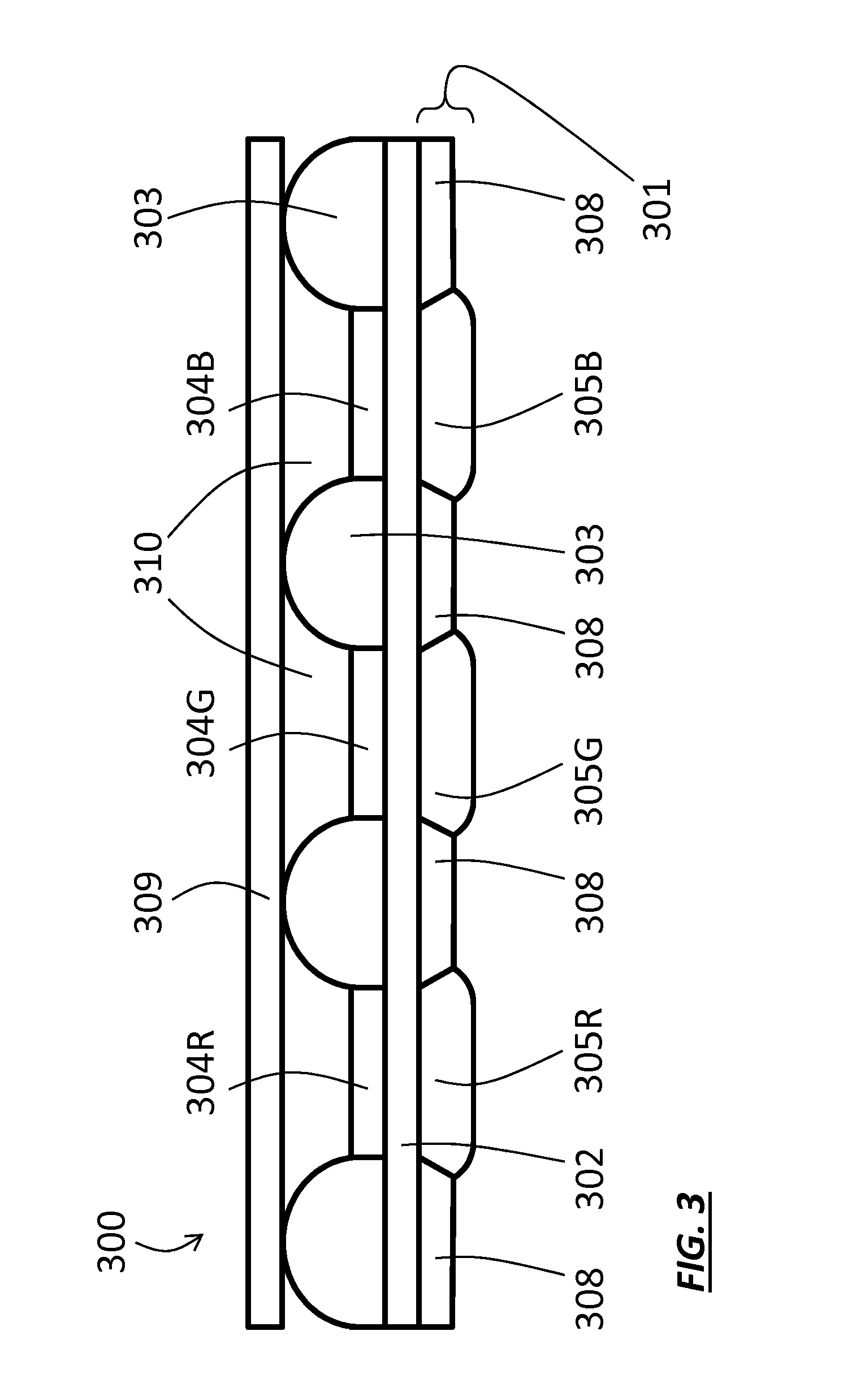
[0089]FIG. 3 depicts a first embodiment of the present invention. Panel 300 comprises electro-optical elements 304R, 304G, 304B formed over a lower substrate 301. Electro-optical elements 304R, 304G, 304B are part of a two-dimensional array of electro-optical elements 304 formed over the substrate 301. (Two-dimensional arrays of elements are discussed further, below, in context of FIG. 22.) Lower substrate 301 comprises a matrix 308 having light-transmissive local seals 305R, 305G, 305B formed as windows in the matrix 308. In preferred embodiments, and as shown in FIG. 3, each electro-optical element 304R, 304G, 304B has a respective local seal 305R, 305G, 305B positioned directly below it. Between lower substrate 301 and electro-optical elements 304R, 304G, 304B there may be intermediate layers variously including one or more of buffer layers, planarization layers, dielectric layers, banks, passive wiring layers, and active TFT layers: these are collectively represented in FIG. 3 b...

second embodiment

[0111]Turning now to FIG. 4A, panel 400 (shown in top view) is a preferred second embodiment of a lighting panel comprising light emitting elements 404 separated by banks 303.

[0112]Local seals 405 lie beneath each light-emitting element 404. The lighting panel may be part of a lighting fixture or other lighting product, either as a removable part or as an integrally fabricated component. FIG. 21F, adapted from U.S. Pat. No. 7,638,941 shows a ceiling-mount OLED chandelier 2160; each OLED panel 2167 is a removable unit.

[0113]Each light-emitting element 404 has a respective local seal 405. As shown, the local seals 405 are hexagonal and are arranged in a hexagonal pattern forming a two-dimensional array. Light-emitting elements 404 and local seals 405 are arranged in similar hexagonal patterns. Of course, other patterns are possible. For example, FIG. 21E, adapted from U.S. Pat. No. 6,870,196, shows an OLED lighting panel 2150 comprising a rectangular array of polygonal lighting elemen...


PUM

PropertyMeasurementUnit
areaaaaaaaaaaa
temperatureaaaaaaaaaa
temperaturesaaaaaaaaaa

Abstract

An electroluminescent display or lighting product incorporates a panel comprising a collection of distinct light-emitting elements formed on a substrate. A plurality of distinct local seals are formed below respective individual light-emitting elements or groups of light-emitting elements. Some embodiments combine a metal foil substrate and glass local seals in a flexible bottom-emitting product. The local seal may be used in conjunction with a continuous thin film encapsulation structure. Optical functions can be provided by each local seal, including refraction, filtering, color shifting, and scattering. Each local seal is formed by depositing a low melting temperature glass powder suspension or paste using inkjet technology, and fusing the glass powder using a scanning laser beam having a tailored beam profile. In other embodiments, a lower encapsulation substrate incorporating local window seals is wholly or partially pre-formed.

Description

CROSS REFERENCE TO RELATED APPLICATIONS[0001]This patent is a continuation-in-part of commonly assigned, co-pending U.S. patent application Ser. No. 14 / 446,470, filed Jul. 30, 2014, titled “Local Seal For Encapsulation Of Electro-Optical Element On A Flexible Substrate” by Rohatgi, since published as U.S. 2015 / 0034934 A1, which claims the benefit of U.S. Provisional Application 61 / 859,989, filed Jul. 30, 2013.FEDERALLY SPONSORED RESEARCH[0002]Not applicable.FIELD OF THE INVENTION[0003]The present invention relates to encapsulation of a flexible electroluminescent device or similar electro-optical panel.BACKGROUND[0004]Electro-optical arrays are widely used in commercial products. Examples of such products include a phone, a monitor, a television set, and a wristwatch, all of which have pixel arrays used for information display. Further examples include an OLED lighting panel and an OLED luminaire, which have arrays of OLED elements used for illumination.Display Products[0005]In rece...

Claims


Application Information

Patent Timeline
Patent Type & Authority Applications(United States)
IPC IPC(8): H01L51/52G02B26/00G02F1/01H01L51/00H01L27/32
CPCH01L51/5246H01L51/0097H01L27/3244H01L2251/5338G02F1/01G02B26/005H01L51/5253H10K59/12H10K50/841H10K50/844H10K2102/311H10K50/84H10K50/8426H10K59/00H10K71/00H10K59/90C03C27/02
Inventor ROHATGI, RAJEEV
Owner GLOBAL OLED TECH
Why Eureka
Try Eureka