Sun protection device

a technology for sun protection and elements, applied in solar heat collector controllers, solar heat collectors with working fluids, solar heat collectors for particular environments, etc., can solve the problems of additional energy required for the purpose of air conditioning or cooling, further deterioration of building energy balance, and mechanical damage of sun protection elements, so as to avoid mechanical damage

Inactive Publication Date: 2015-07-09
FRAUNHOFER GESELLSCHAFT ZUR FOERDERUNG DER ANGEWANDTEN FORSCHUNG EV
View PDF8 Cites 9 Cited by
  • Summary
  • Abstract
  • Description
  • Claims
  • Application Information

AI Technical Summary

Benefits of technology

[0028]In some embodiments of the invention, the sun protection elements can be in contact with a solar absorber via at least one boundary edge. This enables the controlled heating and cooling of the sun protection elements. The solar absorber can have a coating that absorbs in a spectrally selective fashion to achieve a settable heating behavior upon

Problems solved by technology

However, in summer, when the external temperatures are higher and/or when the solar radiation is very high, the rooms behind the windows strongly heat up, and therefore additional energy is required for the purpose of air conditioning or cooling.
This considerably deteriorates the energy balance of the building, and therefore it is often desirable to temporarily shadow at least one window opening.
This known sun protection device has the drawback that it either cannot be o

Method used


Image

  • Sun protection device
  • Sun protection device
  • Sun protection device

Examples


first embodiment

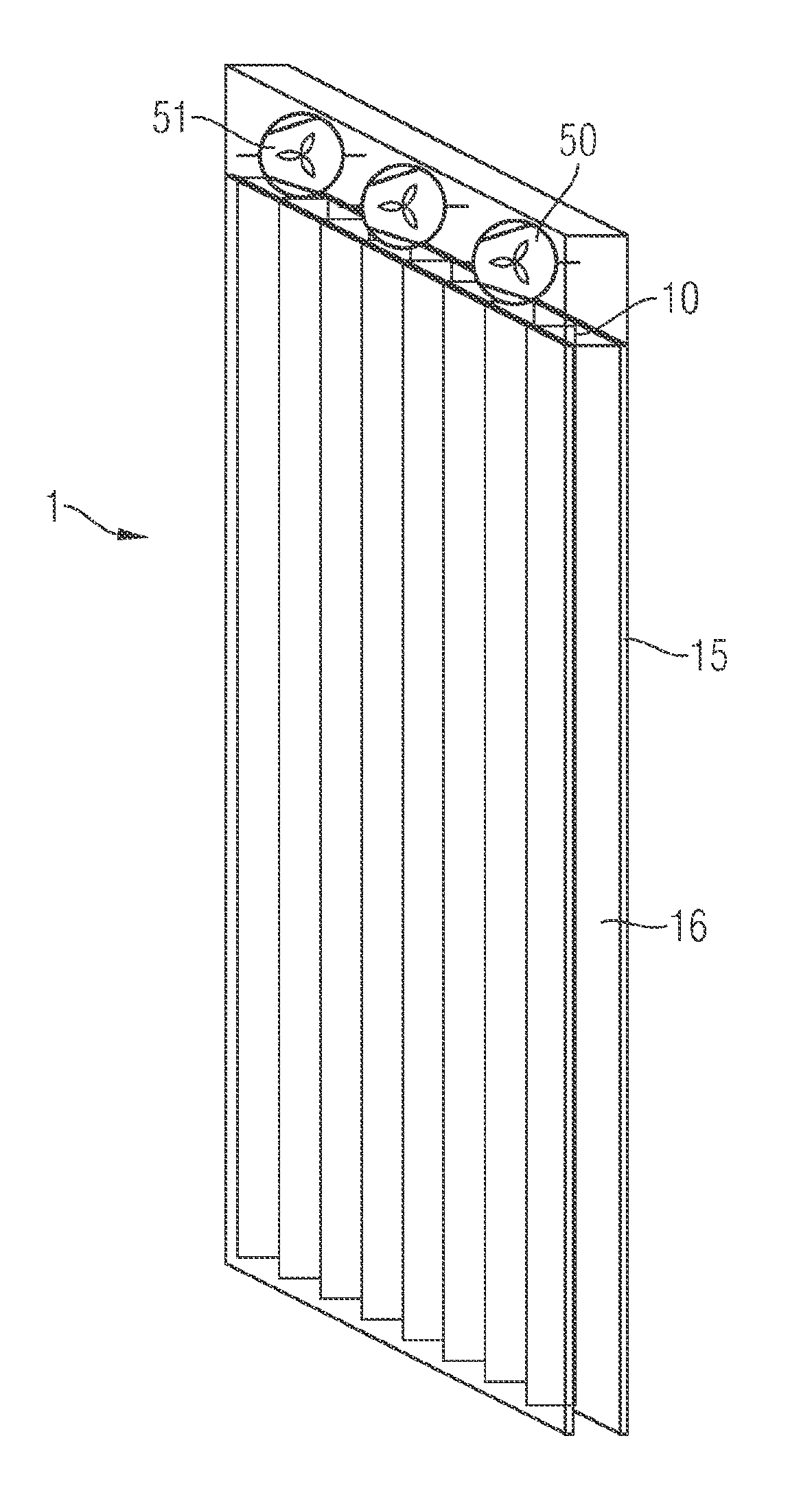
[0044]FIG. 1 shows a sun protection device according to the invention. The sun protection device 1 comprises a plurality of sun protection elements 10 which are arranged between two transparent or translucent panes 15. This serves for avoiding mechanical damage to or the influence of precipitation on the sun protection elements 10. The sun protection elements include a front face having a comparatively small cross-section. In some embodiments of the invention, this cross-section can be between about 1 mm and about 10 mm. Furthermore, the sun protection elements have a width of about 10 mm in a direction orthogonal to the panes 15. In other embodiments of the invention, this width can vary from about 3 mm to about 50 mm. As a result, only the narrow front face of the sun protection elements 10 is visible in the open position thereof. The sun protection elements 10 only fill the intermediate space 16 in the closed position and increasingly shadow the room therebehind, as will be expla...

second embodiment

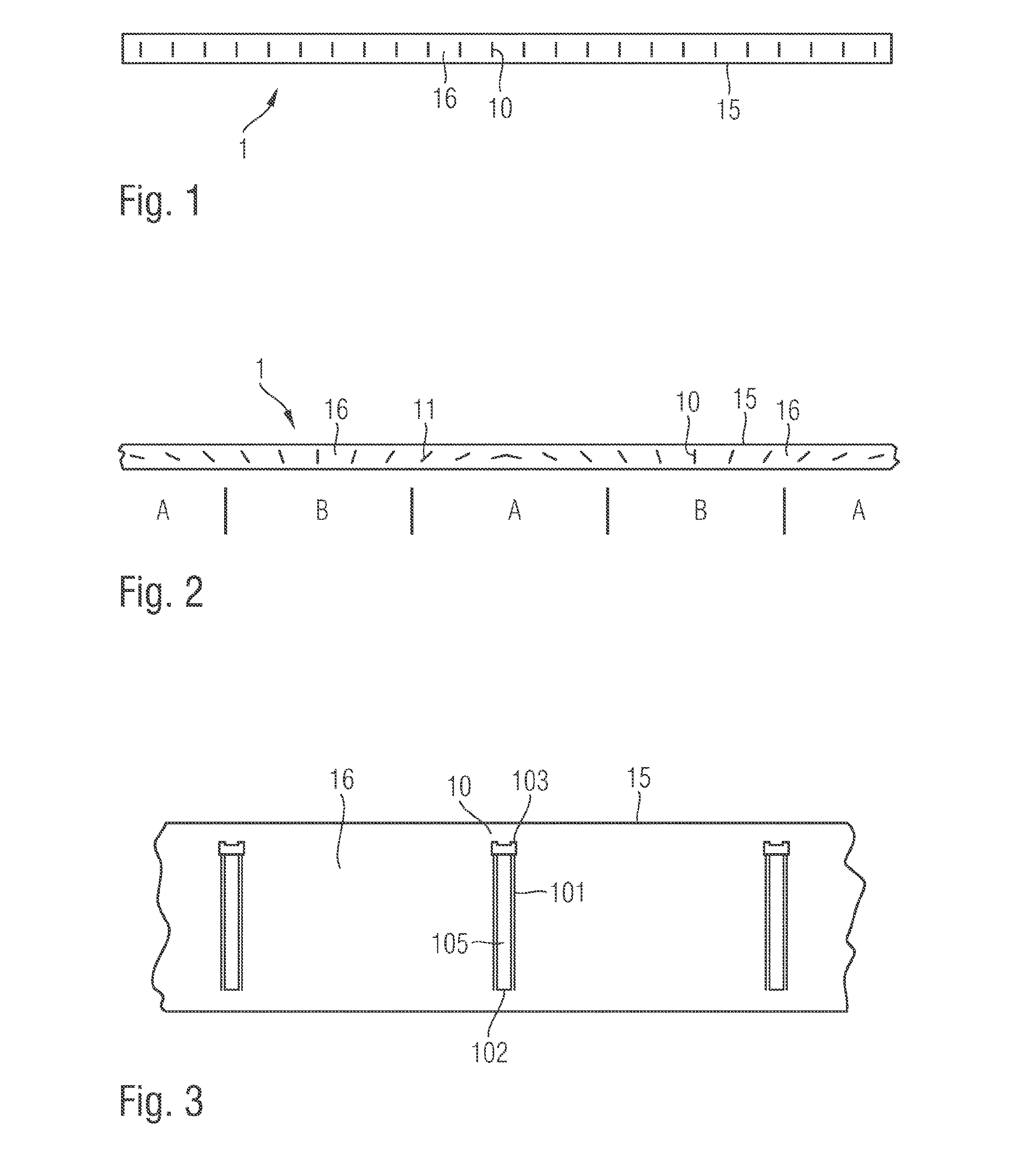
[0045]the invention is explained by means of FIG. 2. The sun protection elements 10 are arranged between two panes 15 in this case as well. However, the sun protection elements 10 are not arranged parallel to one another but at different angles of inclination. Furthermore, the sun protection device 1 according to FIG. 2 contains the adaptive sun protection elements 10 which are explained by means of FIG. 4 and also conventional sun protection elements 11 having constant cross-section. According to FIG. 2, the window opening is divided into different sections which are marked by A and B in FIG. 2. Adaptive sun protection elements 10 are inserted in sections B and shadow a relatively large or small portion of the panes 15 depending on the thermal influence. In sections A, however, conventional sun protection elements 11 are inserted and shadow a constant portion of the window area.

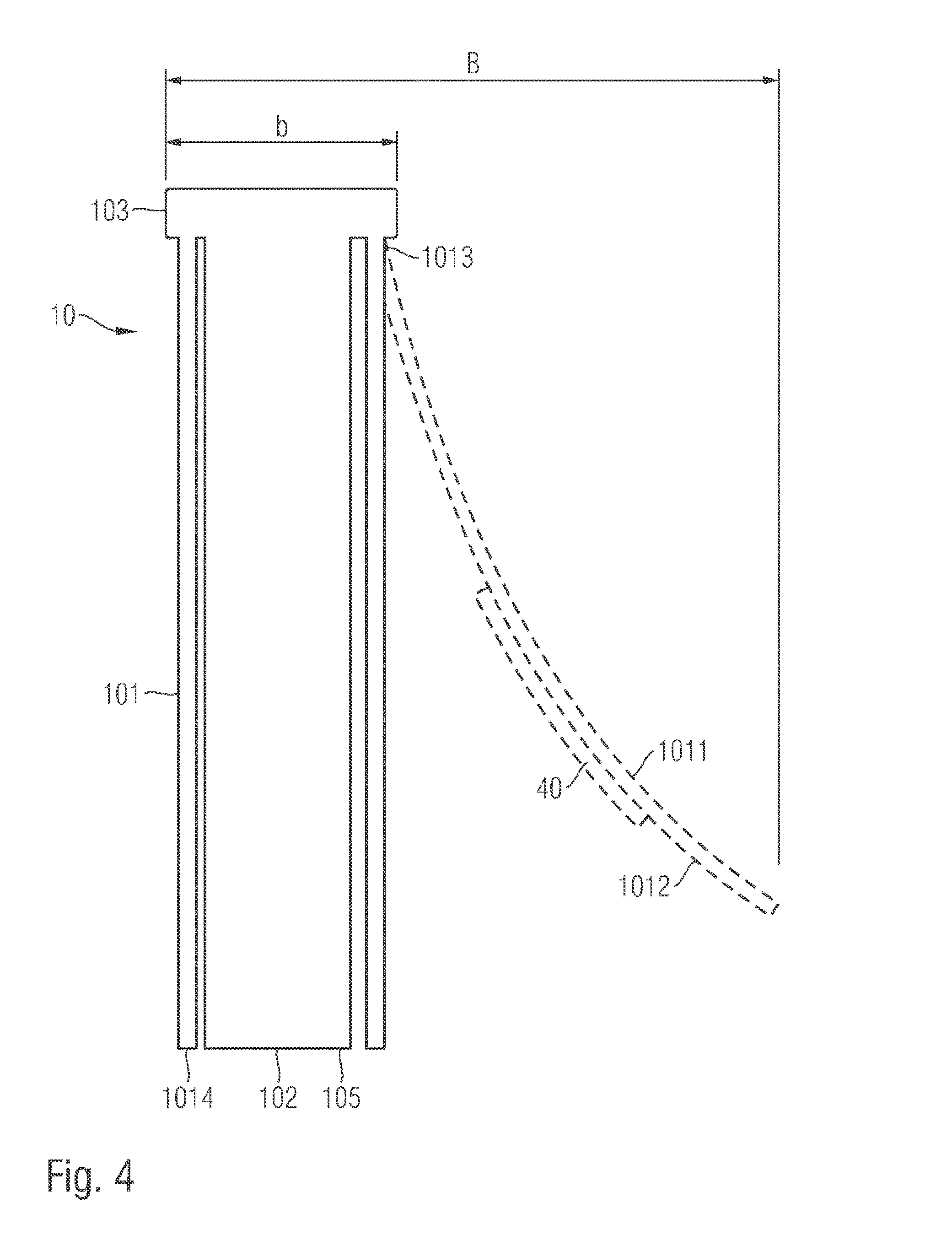
[0046]The functioning principle of a sun protection element 10 is explained in more detail by means of FI...

third embodiment

[0063]the invention is explained in more detail by means of FIG. 11. FIG. 11 shows a sun protection device 1 having a plurality of sun protection elements 10. Each sun protection element 10 has a housing 32, in which a flexible membrane 33 is arranged. Each sun protection element 10 is connected to a reservoir 30 via a hydraulic line 31, said reservoir containing a hydraulic fluid. The reservoir 30 is provided with a solar absorber 301. As shown in FIG. 12, the solar absorber 301 absorbs thermal energy when the weather is favorable, thus heating the hydraulic fluid in the reservoir 30. This leads to a thermal expansion, and therefore a pressure is built up in the hydraulic line 31. This pressure leads to an extension of the membrane 33 from the housing 32. As a result, the window opening provided with the sun protection device 1 is increasingly shadowed.

[0064]In order to manually influence the sun protection elements 10, the hydraulic fluid can be heated with an additional heater, e...


PUM


Abstract

The invention relates to a sun protection device having sun protection elements, where each of the sun protection elements have a housing in which a flexible membrane is arranged, where each sun protection element is connected to a reservoir containing a hydraulic fluid by means of a hydraulic line, the reservoir including a solar absorber, where the membrane is adapted to extend from the housing if the pressure in the hydraulic line increases.

Description

[0001]This application is a national stage entry of International Patent Application PCT / EP2013 / 065427, filed Jul. 22, 2013, entitled “SUN PROTECTION DEVICE,” the entire contents of which are incorporated by reference, which in turn claims priority to German patent application 102012212848.4, filed Jul. 23, 2012, entitled “SONNENSCHUTZVORRICHTUNG”, the entire contents of which are incorporated by reference.BACKGROUND OF THE INVENTION[0002]The invention relates to a sun protection device comprising a plurality of movable sun protection elements which can be moved from an open position to a closed position.[0003]It is known from experience to equip buildings with windows and / or glass facades. They allow the users of the building to view the environment, on the one hand, and also the entry of solar energy into the building, on the other hand. This can be beneficial in winter to save heating costs. However, in summer, when the external temperatures are higher and / or when the solar radia...

Claims


Application Information

Patent Timeline
IPC IPC(8): E05F17/00E06B9/36
CPCE05F17/00E05F2017/005E06B9/36E06B9/24E06B9/26E06B2009/2476Y02E10/44F24S10/00F24S70/65F24S2020/183F24S50/80
Inventor SCHMOHL, ANDREASSCHWITALLA, CHRISTOPHBREUER, KLAUS
Owner FRAUNHOFER GESELLSCHAFT ZUR FOERDERUNG DER ANGEWANDTEN FORSCHUNG EV
Why Eureka
Try Eureka