Fuel cell vehicle

a fuel cell and vehicle technology, applied in the direction of cell components, vehicle sub-unit features, propulsion by batteries/cells, etc., can solve the problems of difficult arrangement of such housings in a space below the floor panel, high cost of braided bus bars, etc., and achieve the effect of sufficient strength

Active Publication Date: 2015-07-16
TOYOTA JIDOSHA KK
View PDF2 Cites 8 Cited by
  • Summary
  • Abstract
  • Description
  • Claims
  • Application Information

AI Technical Summary

Benefits of technology

[0029]According to the present invention, a fuel cell vehicle can be provided in which a fuel cell casing and a boost converter can be fastened and

Problems solved by technology

Thus, when the fuel cell stack and boost converter are stored in a single large housing, arranging such housing in a space below the floor panel is difficult because the housing and the p

Method used


Image

  • Fuel cell vehicle
  • Fuel cell vehicle
  • Fuel cell vehicle

Examples


Embodiment Construction

[0043]Hereinafter, embodiments of the present invention will be described, with reference to the attached drawings. To facilitate understanding of the descriptions, the same elements will be given the same reference signs wherever possible in each drawing and repetitive descriptions will be omitted.

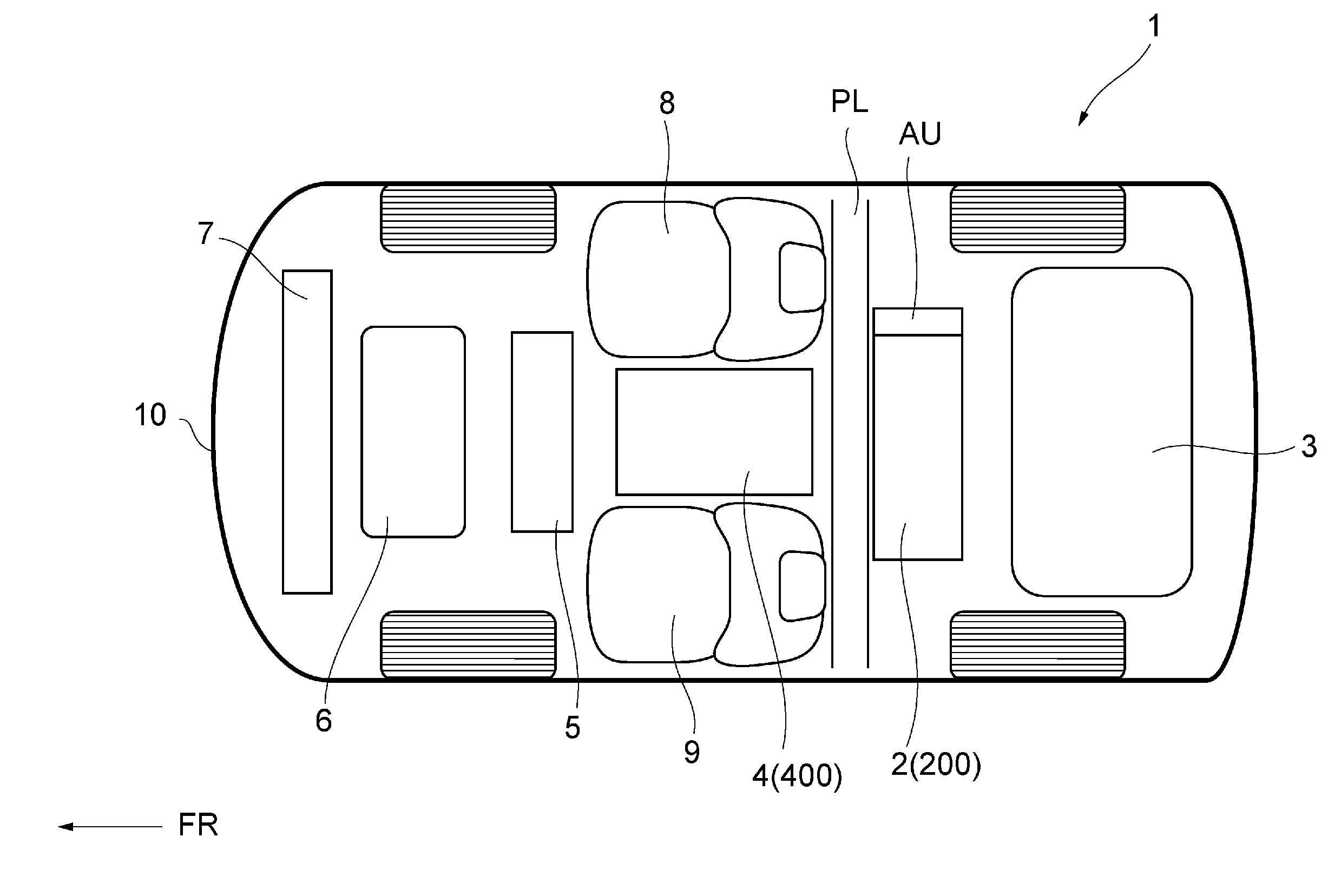
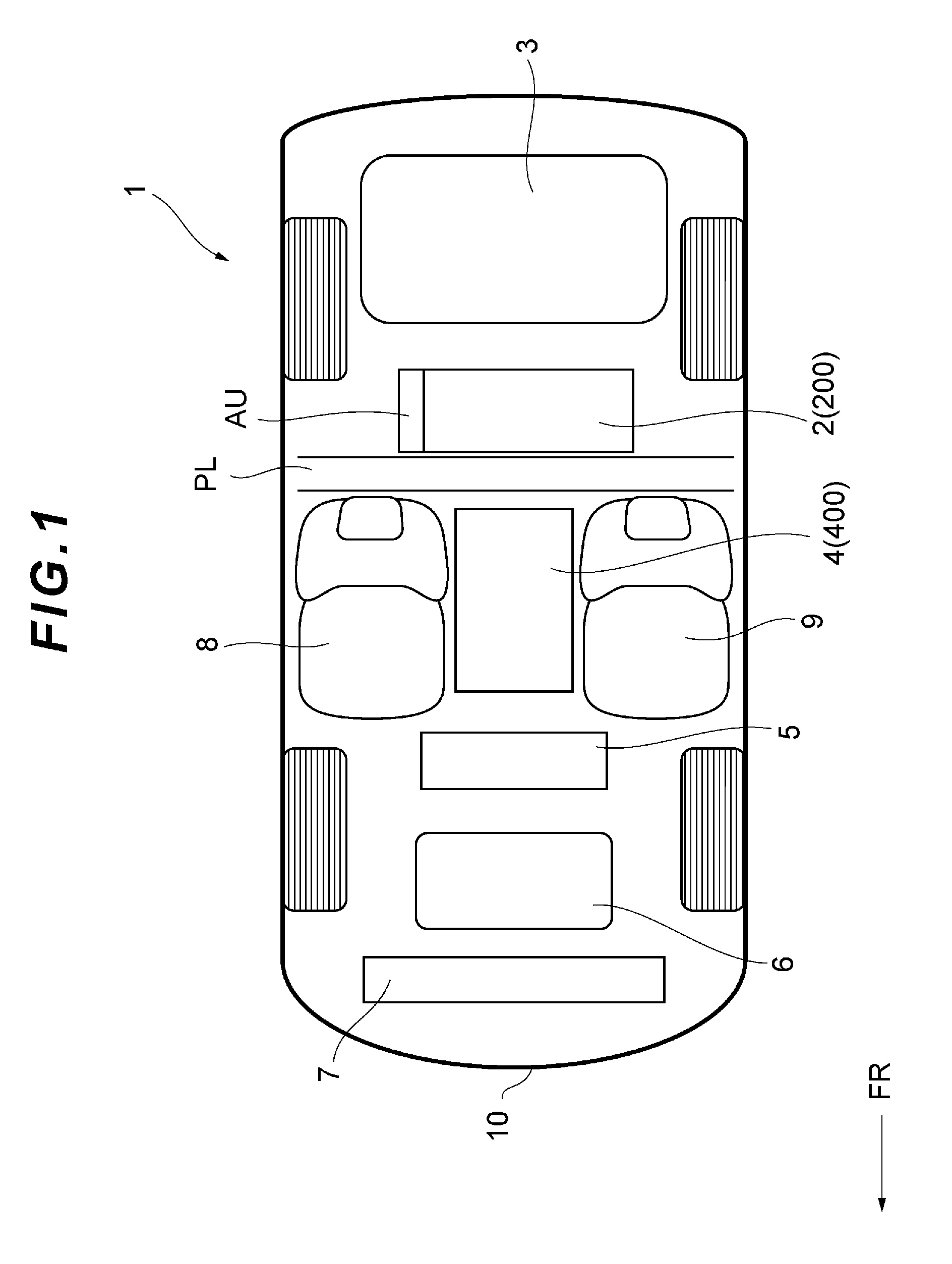
[0044]Firstly, the configuration of a fuel cell vehicle which is an embodiment of the present invention will be described with reference to FIG. 1. FIG. 1 is a view schematically illustrating the configuration of a fuel cell vehicle which is an embodiment of the present invention, when seen from above. As illustrated in FIG. 1, a fuel cell vehicle 1 is constituted by a fuel cell apparatus 2, a fuel tank 3, a DC-DC converter 4, an inverter 5, a traction motor 6 and a radiator 7.

[0045]In the below description, unless otherwise specified, the term “forward” means the travelling direction of the fuel cell vehicle 1 (the direction referred to as “FR” in FIG. 1, etc.) and the term “rearward” me...


PUM


Abstract

A protection bar is arranged between a fuel cell casing and a DC-DC converter in the left-right direction of a fuel cell vehicle. Two fastening surfaces, each being a part of the fuel cell casing, and an FDC flange, which is a part of the DC-DC converter, are fastened and fixed to each other, with one being vertically superimposed on the other, in a space above or below the protection bar.

Description

TECHNICAL FIELD[0001]The present invention relates to a fuel cell vehicle.BACKGROUND ART[0002]In recent years, as a counter-measure against global warming and the future depletion of petroleum, fuel cell vehicles that drive using electric power supplied from a fuel cell system are under development. Such fuel cell vehicle has a fuel cell stack in which a plurality of fuel cells is connected in series, and a boost converter that outputs electric power by increasing output voltage of the fuel cell stack.[0003]Usually, both the fuel cell stack and the boost converter are arranged in a space below the floor panel in order to ensure a large seating space for passengers. As described in Patent Document 1 indicated below, one possible arrangement is for the fuel cell stack and boost converter to be stored in a single housing and the housing to be arranged in a space below the floor panel.[0004]However, a protection bar for suppressing distortion of the vehicle in a side crash is arranged b...

Claims


Application Information

Patent Timeline
IPC IPC(8): B60L11/18H01M8/24H01M8/04
CPCB60L11/1883H01M8/0494H01M2250/20B60L11/1896H01M8/2475B60K1/00B60K1/04B60L2210/14B60K2001/0416B60Y2306/01B60L50/72B60L50/71Y02T10/72Y02T90/40Y02T10/70Y02T10/7072Y02T90/14Y02E60/50Y02T90/12B60L53/22
Inventor KATANO, KOJISEKINE, HIROYUKINAKAMURA, IKUHIRO
Owner TOYOTA JIDOSHA KK
Why Eureka
Try Eureka