Electric Brake Booster with Transmission Clearance Compensation

Active Publication Date: 2015-07-16
ROBERT BOSCH GMBH
View PDF8 Cites 11 Cited by
  • Summary
  • Abstract
  • Description
  • Claims
  • Application Information

AI Technical Summary

Benefits of technology

[0004]To this end, the invention relates to an electric brake booster of the type defined above, characterized in that the shafts are free in translation relative to the screw and to the body of the electric brake booster but are integrally interconnected in the translational movement thereof.
[0005]The freedom provided to the two shafts carrying the worm gears meshing with the screw carried by the output shaft of the drive motor makes it possible to naturally balance the engagement clearance of the racks, the spur gears meshing with the racks being able to move in translation along the geometric axis thereof relative to the racks. Since the angle of the teeth of the two worm gears in the symmetrical positions, in the region of contact thereof with the screw, have slopes inclined in opposite directions relative to the plane of symmetry passing through the axis of the screw and the axis of the booster piston, a balancing position making it possible to engage the two racks with the same force or the same torque is necessarily reached.
[0006]This balancing movement corresponds to a translation of the two shafts with the worm screws so as to move up or down slightly relative to the median plane passing through the geometric axis of the screw.
[0007]Consequently, this natural balancing of the two symme

Problems solved by technology

However, the clearance that must be left for the booster piston is not suitable for the

Method used


Image

  • Electric Brake Booster with Transmission Clearance Compensation
  • Electric Brake Booster with Transmission Clearance Compensation
  • Electric Brake Booster with Transmission Clearance Compensation

Examples


Embodiment Construction

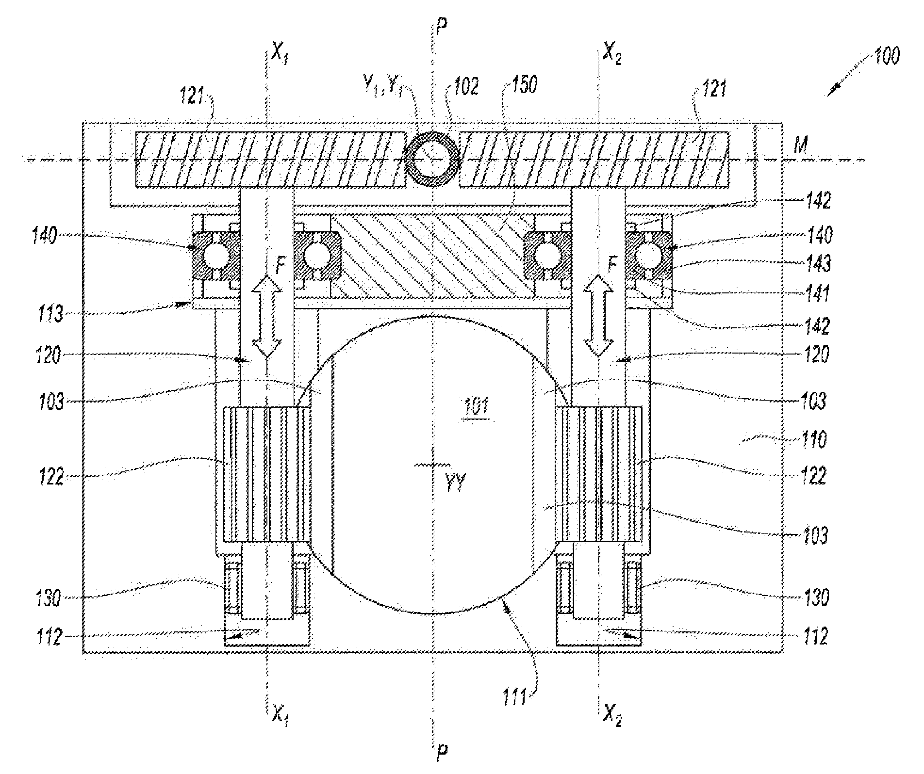
[0026]According to FIG. 1, the invention relates to an electric brake booster 100 acting by means of a booster piston 101 on the master-cylinder of the brake system. Neither the master-cylinder nor the brake system downstream of the master-cylinder with the brake wheels is shown. The figure is limited to a very schematic sectional view of the electric brake booster 100 perpendicular to the axis of the booster piston 101 at the transmission driving the booster piston from the output shaft 102 of the electric motor, which also is not shown.

[0027]The electric brake booster 100 is formed of a body 110 housing the booster piston 101 guided in a cylinder 111 along an axis of translation yy perpendicular to the plane of FIG. 1.

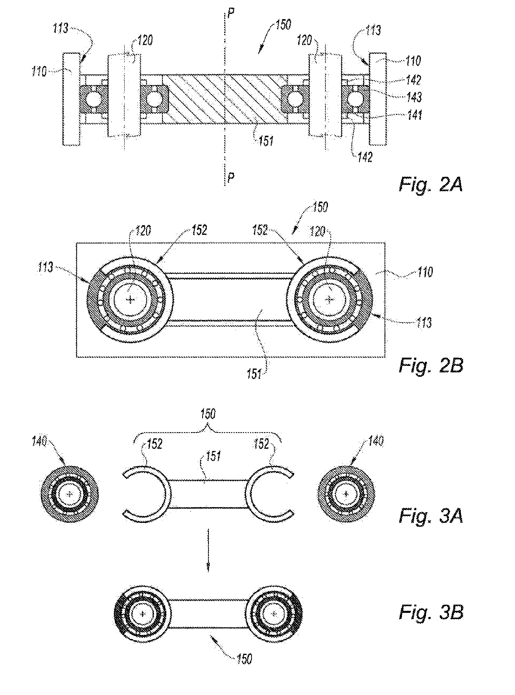
[0028]The electric motor has an output shaft carrying the screw 102 of geometric axis perpendicular to the plane of FIG. 1. This screw 102 drives two transmission shafts 120, which are symmetrical with respect to the median plane PP passing through the geometric axis...


PUM


Abstract

An electric brake booster includes an electric motor activating a booster piston acting on the master-cylinder during brake pedal activation. The booster piston is driven in the direction of the action of same on the master-cylinder by an electric motor linked to a mechanical transmission that includes a screw held by the motor shaft. The screw meshes with two symmetrical worm gears that are integral with respective transmission shafts housed in a bearing of the body of the brake booster. The two shafts each carry a spur gear that meshes with a rack of the booster piston. The shafts are free in translation relative to the screw and to the body of the electric brake booster but are integral with each other in the translational movement of same. The shafts are integrally connected in translation by a coupling member formed by a crosspiece carrying two rotation bearings.

Description

FIELD OF THE INVENTION[0001]The present invention relates to an electric brake booster comprising an electric motor activating a booster piston acting on the master-cylinder when the brake pedal is activated, the booster piston being driven in the direction of the action of same on the master-cylinder by an electric motor linked to a mechanical transmission comprising a screw carried by the shaft of the motor and meshing with two symmetrical worm gears, each integral with a transmission shaft carrying a spur gear meshing with a rack of the booster piston, each shaft being housed in a bearing of the body of the brake booster.PRIOR ART[0002]Electric brake boosters of the type defined above are known. In these brake boosters, since the booster piston is driven symmetrically, balanced by two symmetrical transmissions relative to the plane passing through the axis of the booster piston and the drive screw, but since mechanically it is impossible to have perfect symmetry, in order to bala...

Claims


Application Information

Patent Timeline
IPC IPC(8): B60T13/74
CPCB60T13/745B60T13/741F16D65/18F16D2121/24F16D2125/42F16D2125/48F16D2125/52
Inventor WINKLER, ROMANRICHARD, PHILIPPECAGNAC, BASTIENGAFFE, FRANCOISRITT, JEAN-MARC
Owner ROBERT BOSCH GMBH
Why Eureka
Try Eureka