

Asymmetric auxiliary group
a technology of auxiliary groups and auxiliary groups, applied in the field of chiral reagents, can solve the problems of low isolation yield of monomers, low yield of oligonucleotide derivatives, and chemical instability of further obtained monomers
- Summary
- Abstract
- Description
- Claims
- Application Information
AI Technical Summary
Benefits of technology
Problems solved by technology
Method used
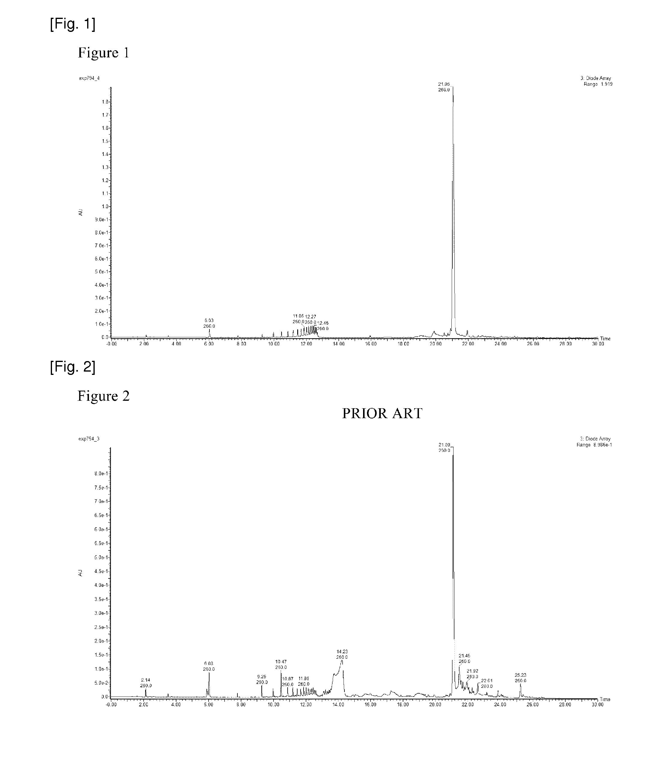
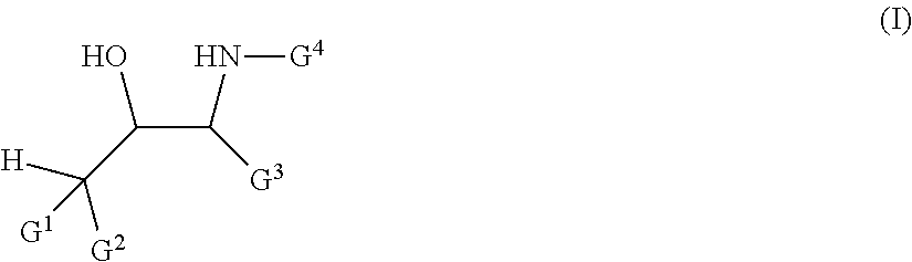
Image


Examples
example 1
(S)-1-Tritylpyrrolidin-2-carbaldehyde (I-a)
[0217]
[0218]Compound I-a was synthesized from L-proline according to the procedure described in the literature (Guga, P. Curr. Top. Med. Chem. 2007, 7, 695-713.).
Example 2
(R)-1-Tritylpyrrolidin-2-carbaldehyde (I-b)
[0219]
[0220]Compound I-b was synthesized from D-proline in a similar manner to compound I-a.
example 3
(S)-2-(Methyldiphenylsilyl)-1-((S)-1-tritylpyrrolidin-2-yl)ethanol (II-a)
[0221]
[0222]To a solution of methyldiphenylsilylmethyl magnesium chloride in THF prepared from chloromethyldiphenylmethylsilane (4.02 g, 16.3 mmol) and magnesium (402 mg, 16.3 mmol) in THF (14 mL) was added I-a (2.79 g, 8.14 mmol) in THF (30 mL) solution with ice cooling. After stirring for 1.5 h with ice cooling, the mixture warmed to room temperature and continued stirring for 30 min. Saturated aqueous NH4Cl (100 mL) was added to the reaction mixture at 0 degrees C., and extraction was performed with diethylether (100 mL) for three times. The combined extract was dried over Naz SO4, filtered and concentrated under reduced pressure. The residue was chromatographed on silica gel afforded II-a as a colorless foam (3.91 g, 87%).
[0223]1H NMR (300 MHz, CDCl3) d 7.48-7.08 (25H, m), 4.33-4.23 (1H, m), 3.16-2.89 (3H, m), 2.84 (1H, brs), 1.70-1.54 (1H, m), 1.35 (1H, dd, J=14.7, 6.3 Hz), 1.10 (1H, dd, J=14.7, 8.1 Hz), 1...
example 4
(S)-2-(Methyldiphenylsilyl)-1-((S)-pyrrolidin-2-yl)ethanol (III-a)
[0224]
[0225]II-a (3.91 g, 7.06 mmol) was dissolved in 3% DCA in DCM (70 mL), and stirred for 10 min at room temperature. To the mixture, 1M NaOH (200 mL) was added, and extraction was performed with DCM (100 mL) for three times. The combined extract was dried over Na2SO4, filtered and concentrated under reduced pressure. The residue was chromatographed on silica gel afforded III-a as a light yellow oil (1.99 g, 90%).
[0226]1H NMR (300 MHz, CDCl3) d 7.57-7.52 (5H, m), 7.38-7.33 (5H, m), 3.77 (1H, ddd, J=8.9, 5.4, 3.5 Hz), 3.01 (1H, dt, J=7.4, 3.6 Hz), 2.97-2.79 (2H, m), 2.27 (2H, brs), 1.76-1.53 (4H, m), 1.38 (1H, dd, J=15.0, 9.0 Hz), 1.24 (1H, dd, J=15.0, 5.4 Hz), 0.65 (3H, s); 13C NMR (100.4 MHz, CDCl3) d 137.4, 137.1, 134.6, 134.5, 129.1, 127.8, 69.5, 64.1, 47.0, 25.8, 24.0, 19.6, −3.4. MALDI TOF-MS m / z Calcd for C9H26NOSi [M+H]+ 312.18. found 312.06.
PUM
| Property | Measurement | Unit |
|---|---|---|
| pH | aaaaa | aaaaa |
| chemical formula | aaaaa | aaaaa |
| length | aaaaa | aaaaa |
Abstract
Description
Claims
Application Information