Control device for diesel engine
a control device and diesel engine technology, applied in the direction of electric control, machines/engines, combustion air/fuel air treatment, etc., can solve problems such as deterioration in drive ability, and achieve the effect of reducing the generation of smok
- Summary
- Abstract
- Description
- Claims
- Application Information
AI Technical Summary
Benefits of technology
Problems solved by technology
Method used
Image

Examples
first embodiment
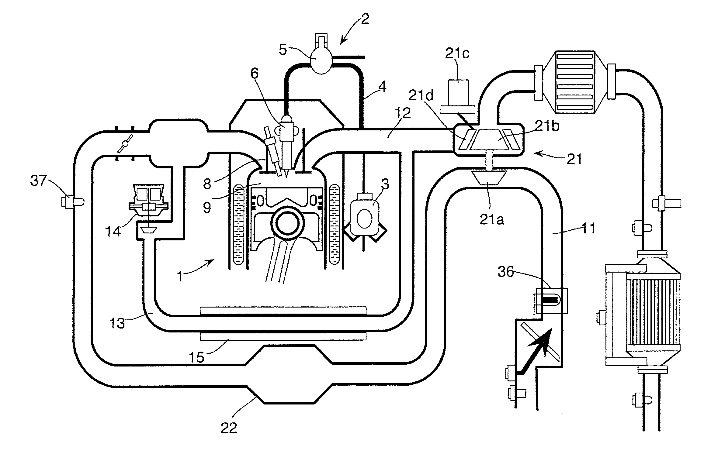
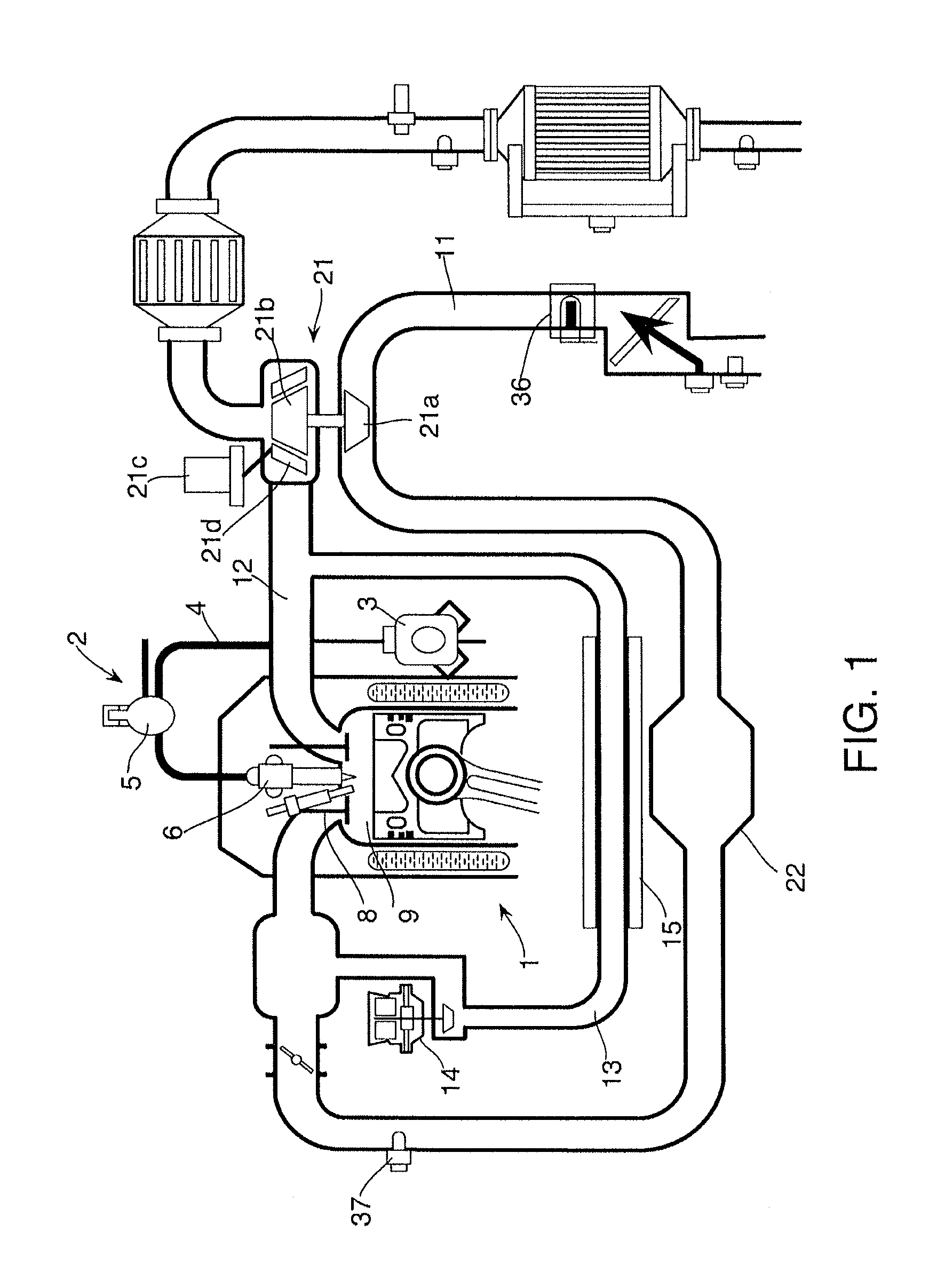
[0028]FIG. 1 is a schematic diagram of a control device for a diesel engine according to a first embodiment of this invention.
[0029]A diesel engine 1 for a vehicle comprises a common-rail fuel injection device 2. The common-rail fuel injection device 2 comprises a supply pump 3, a common rail 5, and fuel injectors 6 corresponding to the number of cylinders of the diesel engine 1. The supply pump 3 applies pressure on fuel and transfers the fuel to the common rail 5 via a fuel supply passage 4. The common rail 5 stores the fuel so as to cause high-pressure fuel. The fuel injectors 6 corresponding to the number of cylinders distribute and supply the high-pressure fuel to the diesel engine 1. Each fuel injector 6 has a three-way valve constituted by a solenoid valve not illustrated. When the three-way valve is an OFF state, a needle-like valve body is in a seated state. When the three-way valve is an ON state, the needle-like valve body is separated from the seat and the three-way valv...
second embodiment
[0126]FIG. 16 is timing charts of parameters during acceleration such as the accelerator position, the target nozzle opening, and the target EGR-valve opening of the diesel engine 1 according to a second embodiment of this invention.
[0127]In the first embodiment, as illustrated by the bold solid line in FIG. 3(B), the given feed-forward amount of the target nozzle opening during acceleration causes switching the target nozzle opening from the first predetermined value VN1 to the third predetermined value VN3 in a stepwise manner at the timing of t3 when the diesel engine 1 is determined to be accelerating. In contrast, in the second embodiment, as illustrated by the single-dotted line in FIG. 16(B), a first-order delay feed-forward amount of the target nozzle opening during acceleration is given at the time t3 when the diesel engine 1 is determined to be accelerating.
[0128]FIG. 17 illustrates a routine for calculating the nozzle opening command value cVN and the EGR-valve opening co...
third embodiment
[0136]FIG. 19 is timing charts of the parameters during acceleration of the diesel engine 1 such as the accelerator operation amount, the target nozzle opening, and the target EGR-valve opening according to a third embodiment of this invention.
[0137]In the first embodiment, as illustrated by the bold solid line in FIG. 3(C), the given feed-forward amount of the target EGR-valve opening during acceleration causes switching the target EGR-valve opening from the first predetermined value EG1 to the second predetermined value EG2 in a stepwise manner at the time t3 when the diesel engine 1 is determined to be accelerating. In contrast, according to the third embodiment, as illustrated by the broken line in FIG. 13(C), a first-order delay feed-forward amount of the target EGR-valve opening during acceleration is given at the time t3 when the diesel engine 1 is determined to be accelerating.
[0138]FIG. 20 illustrates a routine for calculating the nozzle opening command value cVN and the EG...
PUM
 Abstract
Description
Claims
Application Information
 - R&D
- Intellectual Property
- Life Sciences
- Materials
- Tech Scout
- Unparalleled Data Quality
- Higher Quality Content
- 60% Fewer Hallucinations
Browse by: Latest US Patents, China's latest patents, Technical Efficacy Thesaurus, Application Domain, Technology Topic, Popular Technical Reports.
© 2025 PatSnap. All rights reserved.Legal|Privacy policy|Modern Slavery Act Transparency Statement|Sitemap|About US| Contact US: help@patsnap.com