Valve With a Loading Varying Mechanism, and Method of Operating the Same

a technology of varying mechanism and valve element, which is applied in the field of valves, can solve the problems of short life of such valves, increased wear and particle generation, and friction and resultant wear, and achieve the effects of reducing friction between the sealing surface of the valve element and the stationary body of the valve, reducing wear and particle generation, and reducing friction between the sealing surfa

Active Publication Date: 2015-07-16
APN INC
View PDF6 Cites 9 Cited by
  • Summary
  • Abstract
  • Description
  • Claims
  • Application Information

AI Technical Summary

Benefits of technology

[0023]An advantage of the present method and valve is that friction between the sealing surfaces of the valve element and stationary body of the valve is reduced during movement of the valve element, and preferably just before the movement start-up. Reducing the friction between the sealing surfaces when the valve element is moved reduces wear and particle generation in the valve, which in turn reduces leaks and / or contamination. Another advantage of the method is that the load force applied on the valve element is not dependent upon the operating pressure of the valve, as in U.S. Pat. No. 6,193,213.
[0024]Advantageously, the load varying mechanism also allows performing a cleaning / washing cycle without having to dismantle or disassemble the valve. Indeed, when reducing the valve element load to an intermediate cleaning load, a cleaning fluid can be applied to flow through the valve from a purge port, so as to clean all surfaces and grooves by moving the valve element; this intermediate cleaning load being low enough to allow a slight spacing of the valve element from the stationary body. This method is particularly adapted to rotary valve, in which the valve element, which is a rotor, can be rotated at high speeds.
[0025]Another advantage of this method and valve is that, when the valve element is stationary in an operational position, it is possible to apply a much higher load on the valve element than what is typically found in other commercially available valves, and this, without the risk of damaging the valve element. This results in a much higher sealing integrity.
[0026]The load varying mechanism also helps to maintain the same predetermined load scheme, even if some of the characteristics of the components change over time, such as can occur when the biasing element softens or the parts of the valve thermally expand in the case of high temperature applications.

Problems solved by technology

Since the force maintaining the rotor on the stator is relatively high, so is friction and resultant wear.
Because wear occurs when the rotor is turned against the stator, the lifetime of such a valve is short.
Friction between the rotor and the stator causes particles to be generated, further increasing the problems associated with wear.
Leaks are likely to appear, and eventually the valve will have to be repaired or replaced.
This problem may be found in most flat and conical rotary valves available.
At such a pressure level, the required rotor loading force provided by the biasing element is high, and so is friction and resultant wear.
As a result, the overpressure on the rotor is also constant and equally applied whether the rotor is stationary or rotating, which disadvantageously does not allow the load force to be varied.
A further disadvantage may result from using the process fluid within different sections of the valve because this increases the risk of contaminating the fluid.
Another problem arises from the fact that valves are usually tuned at ambient temperature, but are mostly used at different temperatures, from cryogenic temperatures to temperatures of around 350° C. The behavior of each part of the valve may therefore differ greatly depending on the temperature range at which it is operated.
Consequently, a valve can work perfectly when tuned and operated at ambient temperature, but important leakage may occur when the valve is used in a system operated at a different temperature.

Method used


Image

  • Valve With a Loading Varying Mechanism, and Method of Operating the Same
  • Valve With a Loading Varying Mechanism, and Method of Operating the Same
  • Valve With a Loading Varying Mechanism, and Method of Operating the Same

Examples


Embodiment Construction

[0054]Within the following description, similar features of the drawings have been given similar reference numerals. To preserve the clarity of the drawings, some reference numerals have been omitted when they were already identified in a preceding figure.

[0055]The implementations described below are given by way of example only and the various characteristics and particularities thereof should not be considered as being limitative of the scope of the present invention. Unless otherwise indicated, positional descriptions such as “top”, “bottom” and the like should be taken in the context of the figures and should not be considered as being limitative.

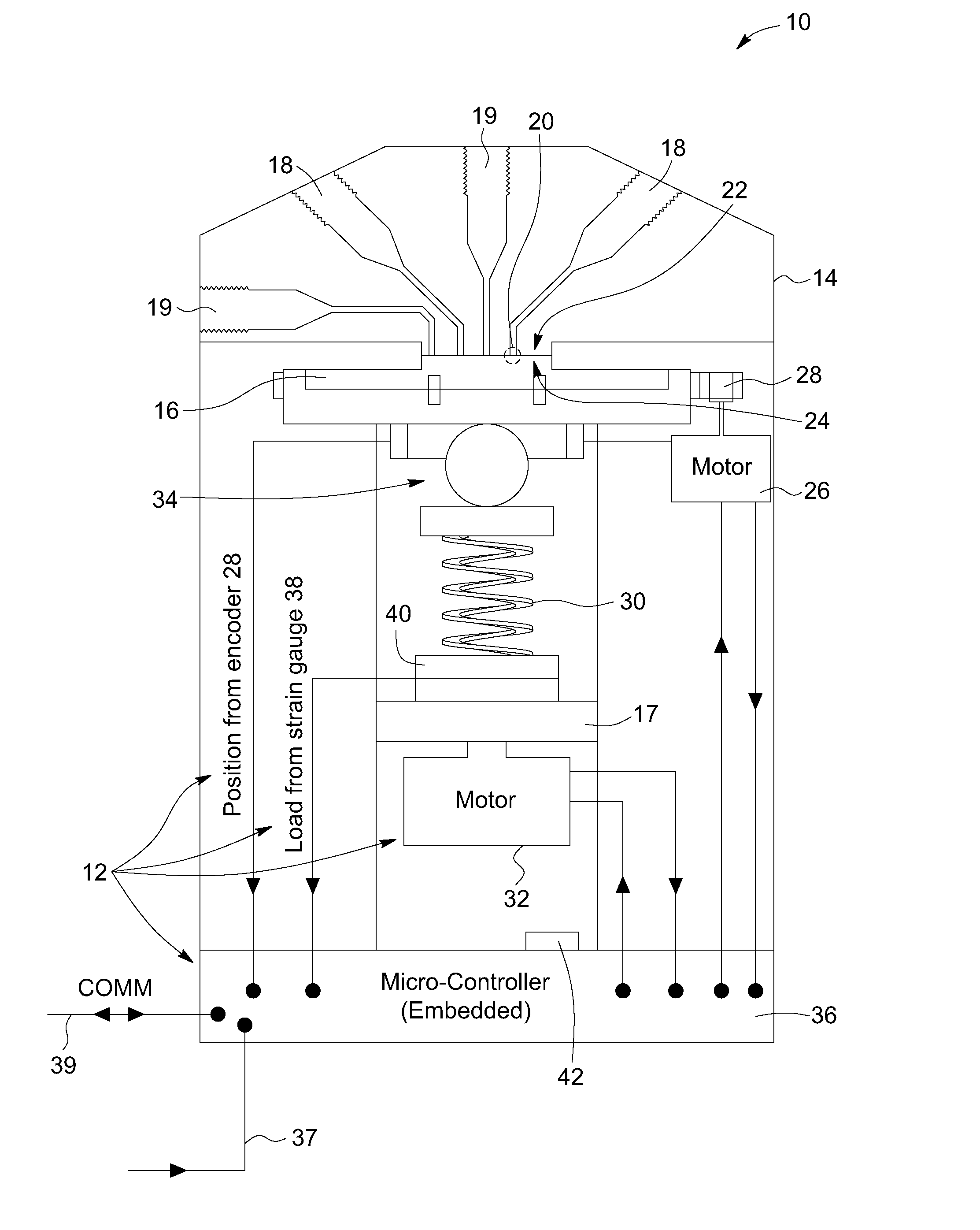
[0056]With reference to FIG. 4, a first implementation of a valve according to the invention is shown. The valve 10 includes a stationary body 14 provided with fluid passages 18 and 19, for circulating fluid therein at a fluid pressure. The fluid passages can also be referred to as channels. The fluid passages include process fluid pass...


PUM


Abstract

A valve is provided. The valve includes a body provided with fluid passages for circulating fluid therein. The body has a body interface with ports connected to the fluid passages. The valve also includes a valve element having a valve element interface facing the body interface. The valve element can move between different positions so as to permit or obstruct communication between the fluid passages. A biasing element biases the valve element interface against the body interface. A load varying mechanism is provided to load the biasing element with different sealing load forces according to the different positions of the valve element. The sealing load force applied on the rotor is thus decreased during rotation, reducing friction between the valve body and the valve element.

Description

FIELD OF THE INVENTION [0001]The present invention generally concerns systems and methods related to valves and more particularly relates to a valve with a load varying mechanism and a method for reducing friction during movement of a valve element.BACKGROUND [0002]Liquid chromatography and auto-sampler systems rely mostly on flat rotary based design valves to handle various fluids. Many different configurations are possible, such as the standard six-port injection valves, valves with syringe port or for sample stream selection, column selection, multi-position / multitask, such as loading, injecting, washing, etc. In most cases, valves have a flat rotor and a flat stator. The flat rotor is pushed against a fixed flat stator. The rotor has various grooves machined in it, allowing different stator port connection schemes to fit any particular application.[0003]To exemplify the description of such a prior art valve system, we will refer to a typical six-port liquid chromatographic valve...

Claims


Application Information

Patent Timeline
Patent Type & Authority Applications(United States)
IPC IPC(8): F16K3/18F16K11/074
CPCF16K3/18F16K3/188F16K11/0743F16K3/10F16K5/201F16K5/166F16K11/0873Y10T137/0318F16K11/0833F16K5/161F16K31/602F16K37/0041G01N30/32G01N2030/328
Inventor GAMACHE, YVES
Owner APN INC
Why Eureka
Try Eureka