Quick comparison circuit

Inactive Publication Date: 2015-07-16
IPGOAL MICROELECTRONICS (SICHUAN) CO LTD
View PDF4 Cites 4 Cited by
  • Summary
  • Abstract
  • Description
  • Claims
  • Application Information

AI Technical Summary

Benefits of technology

The present invention provides a circuit for quickly comparing two signals with high accuracy. The amplifier circuit includes certain FETs that help to quickly rise or fall the voltages of the signals, making the amplification process faster. Additionally, certain other FETs are connected in a way that clamps the signals, reducing the amplitude of the signals and further improving the comparison speed.

Problems solved by technology

However, it's known that mutual restraint appears in the gain and the comparison speed of the amplifier always, which causes a difficulty to achieve both quick comparison and high accuracy at a certain process condition.

Method used


Image

  • Quick comparison circuit
  • Quick comparison circuit
  • Quick comparison circuit

Examples


Embodiment Construction

[0015]Various preferred embodiments of the invention will now be described with reference to the figures, wherein like reference numerals designate similar parts throughout the various views. As indicated above, the invention is directed to a quick comparison circuit having high gain and quick comparison speed.

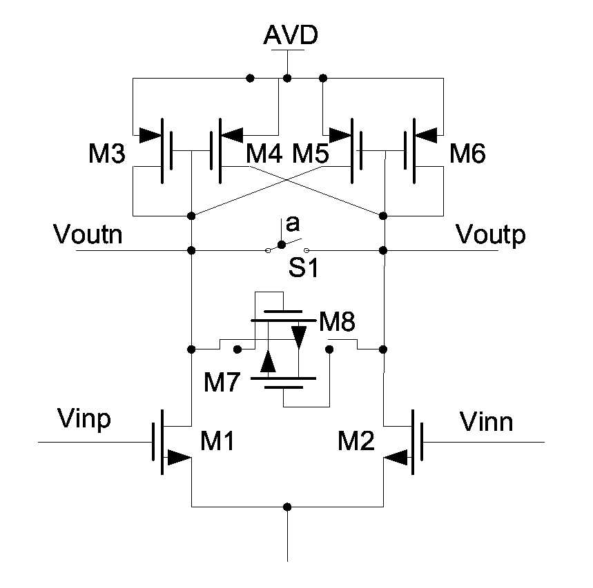
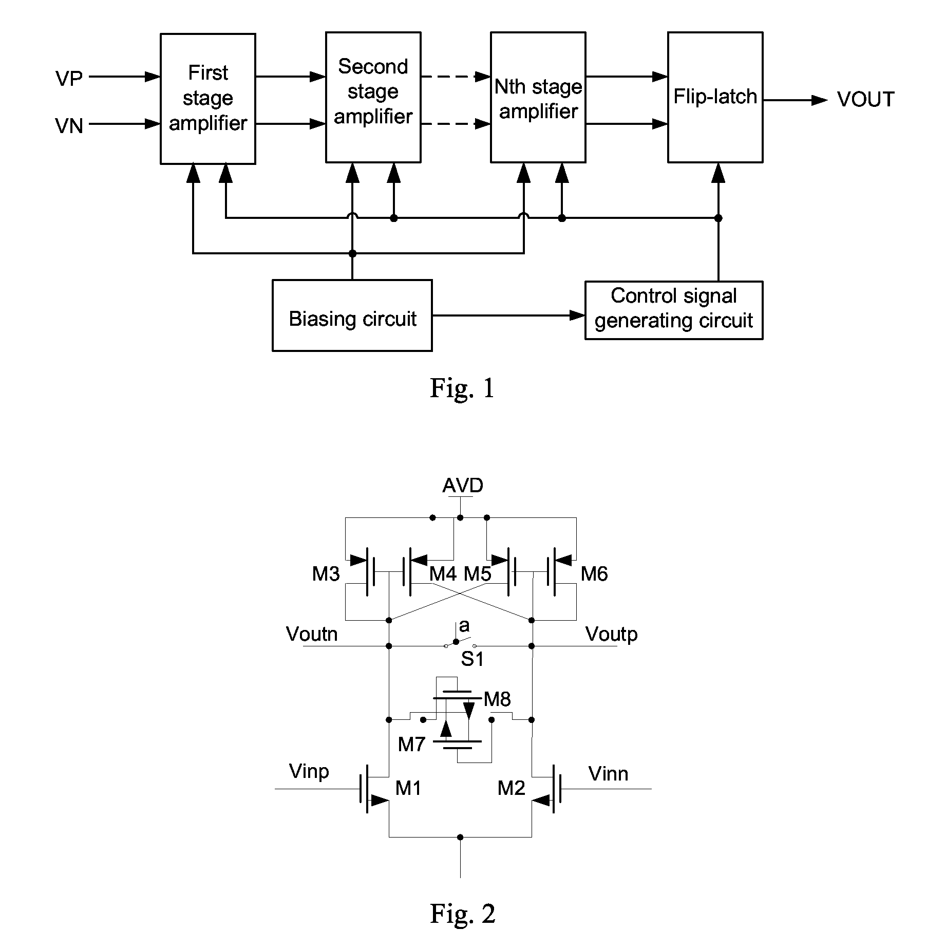
[0016]Referring to FIG. 1 that shows a schematic view of a quick comparison circuit according to one embodiment of the present invention, the circuit includes a cascaded N-stage (N≧2) operational amplifier, a flip-latch, a biasing circuit, and a control signal generating circuit. Two differential signals VP and VN to be compared are inputted to the input terminal of the first stage operational amplifier, the output terminal of the first stage operational amplifier is connected with the input terminal of the second stage operational amplifier, and the output terminal of the second stage operational amplifier is connected with the input terminal of the third stage operational am...


PUM


Abstract

A quick comparison circuit includes a cascaded N-stage operational amplifier, a flip-latch, a biasing circuit, and a control signal generating circuit, with N≧2, and two differential signals to be compared being inputted to an input terminal of a first stage operational amplifier, an output terminal of a Nth stage operational amplifier being connected with an input terminal of the flip-latch, the biasing circuit supplying a biasing current to each stage operational amplifier, the control signal generating circuit being connected with the N-stage operational amplifier and the flip-latch respectively to supply a working time sequence and a reset control signal for them, and each stage operational amplifier having the same structure. This circuit has high gain and improved comparison speed.

Description

RELATED APPLICATIONS[0001]This application claims the benefit of priority to Chinese Patent Application No. 201410020407.0, filed on Jan. 16, 2014, which is hereby incorporated by reference in its entirety.FIELD OF THE INVENTION[0002]The present invention relates to technical field of integrated circuits and, more particularly to a quick comparison circuit.BACKGROUND OF THE INVENTION[0003]Comparison circuits are widely used in conversion process between the analog signals and the digital signals (A / D conversion) which the sampled analog signal will be flowed through an operational amplifier or a comparator to determine its digital value. This operational amplifier utilizes an open-loop mode commonly that no compensation for the operational amplifier is needed, so that the operational amplifier may obtain a wider bandwidth and a higher frequency response. However, it's known that mutual restraint appears in the gain and the comparison speed of the amplifier always, which causes a dif...

Claims


Application Information

Patent Timeline
IPC IPC(8): H03F3/45
CPCH03F3/45076H03F2200/555H03F2203/45171H03F1/0261H03F3/45179H03F2200/405H03F2203/45394H03F2203/45644H03F2203/45728H03K5/2481
Inventor YANG, BAODINGZOU, ZHENGXIAN
Owner IPGOAL MICROELECTRONICS (SICHUAN) CO LTD
Why Eureka
Try Eureka