Garbage Disposal Controls System

a control system and garbage disposal technology, applied in the direction of mechanical control devices, process and machine control, instruments, etc., can solve the problems of inconvenient use, lack of safety warning features, and lack of convenience features of the state of the art, and achieve the effect of low power consumption and small siz

Inactive Publication Date: 2015-07-23
PERKINS ALAN MARK
View PDF26 Cites 9 Cited by
  • Summary
  • Abstract
  • Description
  • Claims
  • Application Information

AI Technical Summary

Benefits of technology

[0027]This Garbage Disposal Controls System represents a major step forward in the ease of use, convenience, and safety of the GD in the residential and industrial commercial environments while preserving the economics associated with currently marketed GDs. That is to say, the GD Controls System does not potentially add greatly to the cost of garbage disposals.
[0037]7. With a form / fit / function (FFF) that can be miniaturized and integrated fully into existing GD products, and can meet requirements for small size, low power consumption, safety, longevity of use for warranty, and cost constraints.

Problems solved by technology

The common garbage disposal in residential and commercial locations lacks safety warning features, lacks convenience features, is almost universally operated by a hand action, and often has the switch located away from the User.
The current state of the art is inconvenient to use, impedes productivity, and is not as safe as it should be.
1. All current implementations inconveniently require either:a) Removing a wet hand / hands from the sink to activate the GD switch;Using a towel to dry off, or dripping on the counter and floor.Stepping away from the sink if the switch is not close enough.Requiring to stay at the switch while the GD is runningUnable to be at the sink to manage the feeding of material to the GD.b) Or, asking someone nearby to push the switch for the User.
2. Current implementations lack safety features:a) No visual warnings such as Light Emitting Diode (LED) indicators.b) No audible warning such as beepers.c) No start delays to operation.
3. Current implementations lack convenience features:a) No One-Touch operation.b) No automatic water injection.
4. The deficiencies of the current state of art waste time, negatively impact productivity, create wet towel to be laundered, and are generally incongruous with smoothly accomplishing tasks at the kitchen sink.
There are few previous commonly implemented solutions to the problems of the state of the art for garbage disposals.
This fails to address all but one of the issues with the current art.a) It does not provide safety features,b) It does not provide convenience features, andc) It still requires the User to stop work with hands at the sink to use it.

Method used


Image

  • Garbage Disposal Controls System
  • Garbage Disposal Controls System
  • Garbage Disposal Controls System

Examples


example embodiment 1

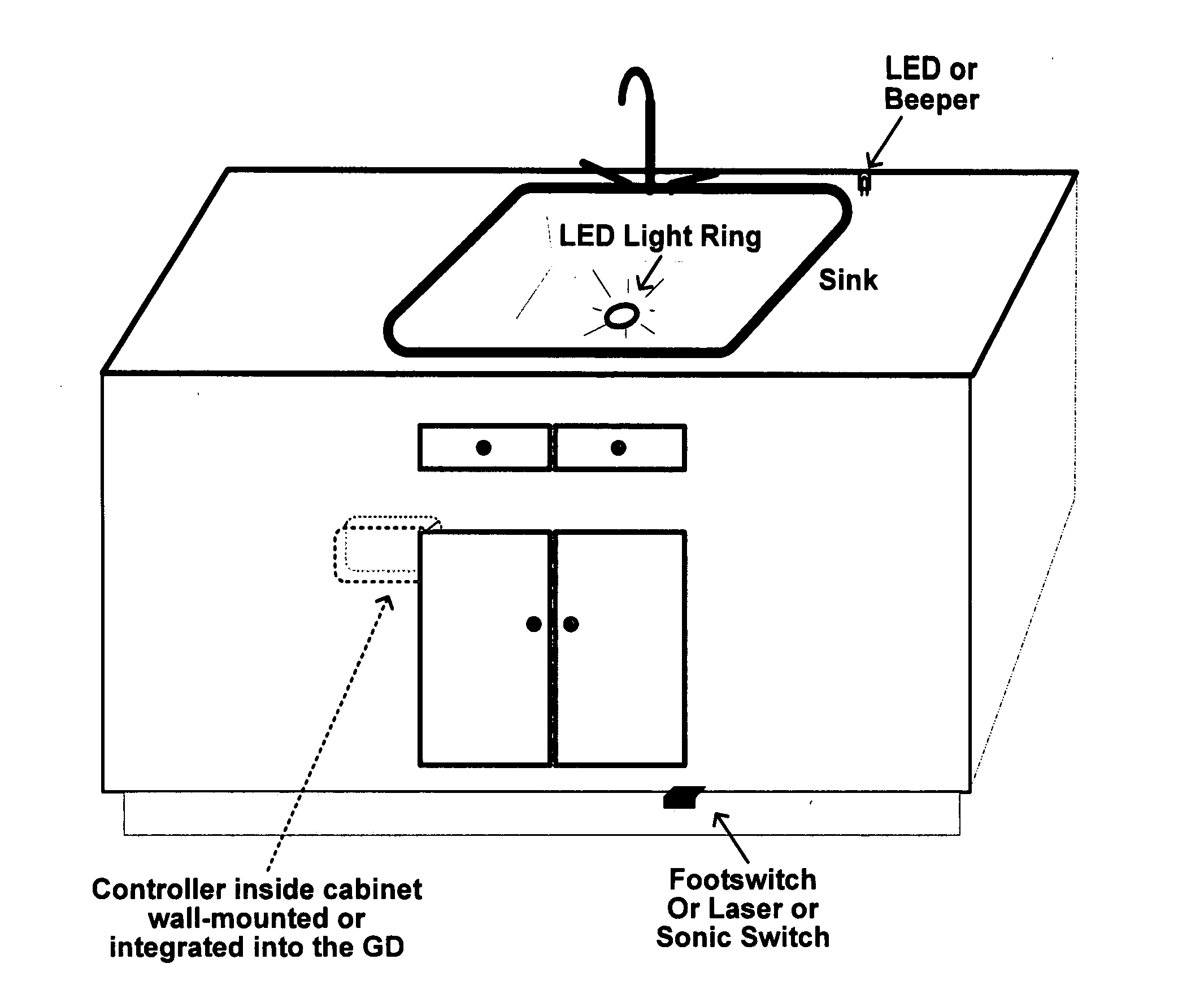
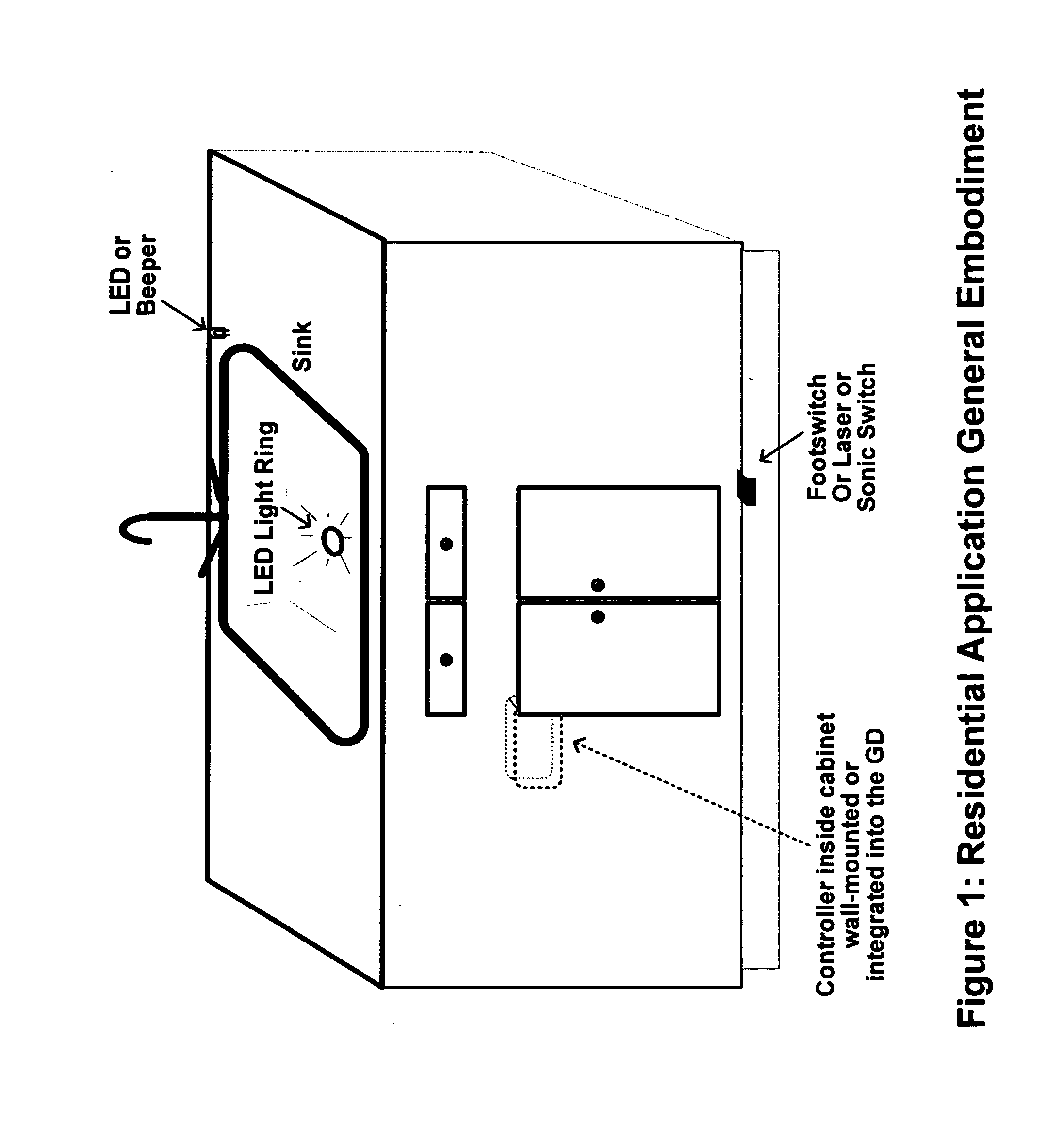
[0096]This example embodiment is a variation of the general embodiment shown in FIG. 1, the residential application using the Add-On version of the GD Controls System. This embodiment shows a residential location where the GD Controls System is installed with these features:[0097]1. The CONTROLLER box is mounted up inside the cabinet on the wall.[0098]2. The CONTROLLER box is plugged into the power socket inside the cabinet.[0099]3. The GD is plugged into the CONTROLLER box power socket.[0100]4. A laser operated foot-switch:[0101]a) The Installer drills a hole into the cabinet base that extends over the floor area to mount the laser module.[0102]b) An adhesive backed reflector is placed on the floor beneath the laser source.[0103]c) The Installer moves the reflector until the LED indicator light on the laser source turns on, indicating that the reflection is returning to the laser sensor, then the Installer attaches the reflector to the floor at that location.[0104]d) When the User ...

example embodiment 2

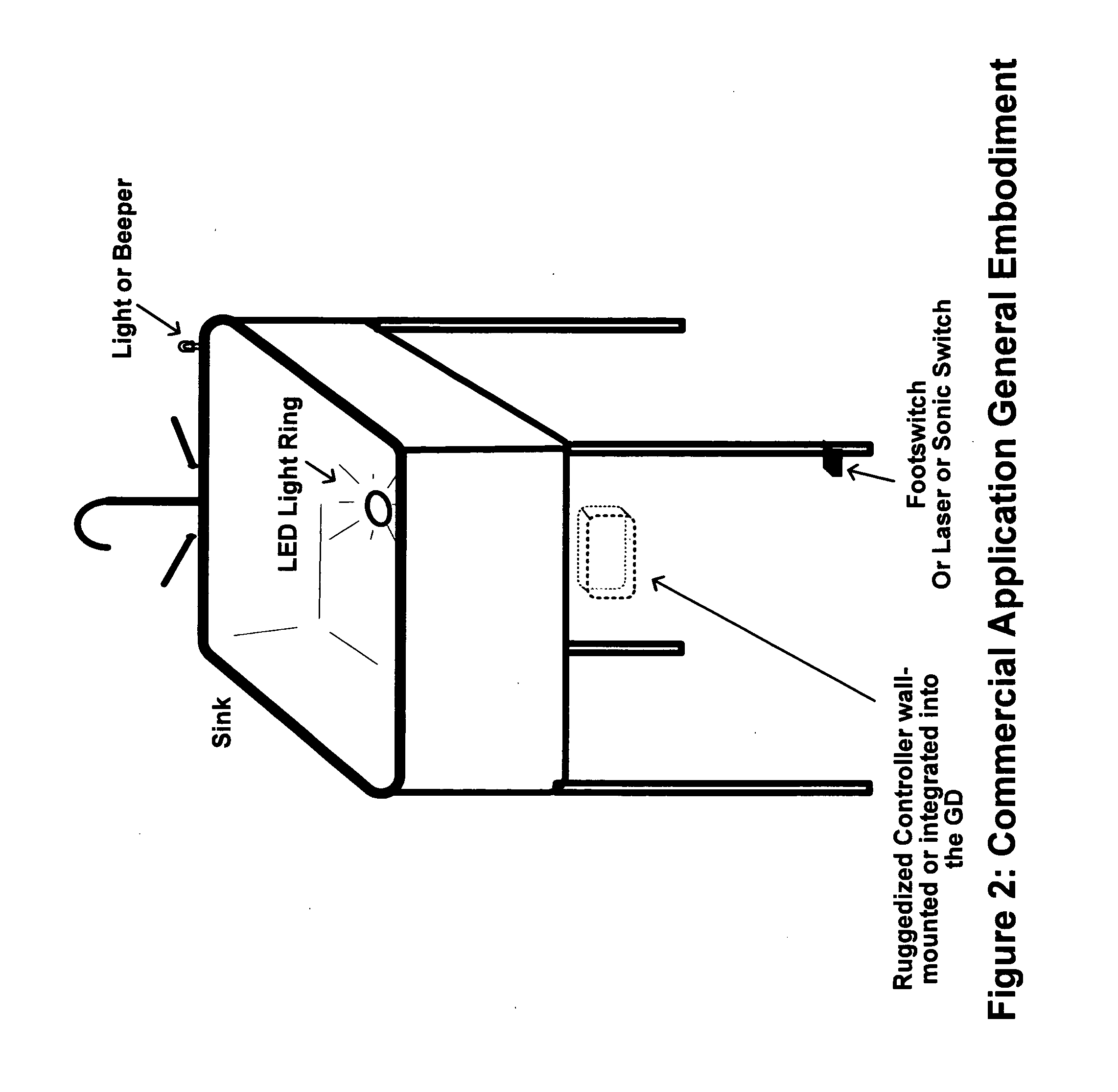
[0108]This example embodiment is a variation of the general embodiment shown in FIG. 2, the commercial application using the Integrated version of the GD Controls System.:[0109]1. The CONTROLLER is integrated into the GD, internal and out of sight.[0110]a) Exiting the GD are the sensors and safety wires.[0111]2. The foot activation switch is mounted to the leg of the sink and sideways facing.[0112]a) The User activates the switch by pressing against it with his / her foot.[0113]b) The usual safe routing of wires to the GD is accomplished with wire covers and so forth.[0114]3. Safety devices:[0115]a) There is a ring LED integrated into the GD sink drain, which lights up during the safety delay period and during the activation period.[0116]b) There is a beeper integrated directly into the GD.[0117]c) There is a third connection available to use for placing an LED safety light on the edge of the sink.


PUM


Abstract

A Garbage Disposal Controls System utility invention that solves the inconvenience problems with using a Garbage Disposal (GD) while also preserving and enhancing safety of the GD for the User. The GD Controls System is applicable to, and provides unique and new functionality to, residential and industrial commercial applications.The invention features are 1) an ability to operate the GD by foot or knee action, 2) an activation delay for safety purposes, delay time being variable and User settable, 3) timed activation of safety devices, 4) a One-Touch capability which controls length of run time, such run time being variable and User settable, 5) automatic water injection during operation, 6) two form factors, which are the Add-On version and the Integrated version.The Garbage Disposal Controls System relies upon micro-controller(or micro-processor) based software that manages sensing and signal interpretation, and carries out sequences of activation actions in timed fashion.

Description

REFERENCES CITED: US PATENT DOCUMENTS[0001]U.S. Pat. No. 6,636,136 B1, October 2003 Vetter—TECHNICAL FIELD[0002]This invention relates to garbage disposal (GD) systems in residential applications and industrial commercial applications.STATE OF PRIOR ART[0003]The common garbage disposal in residential and commercial locations lacks safety warning features, lacks convenience features, is almost universally operated by a hand action, and often has the switch located away from the User. The current state of the art is inconvenient to use, impedes productivity, and is not as safe as it should be. Listed herein is a summary of the deficiencies found in the current state of the art:[0004]1. All current implementations inconveniently require either:[0005]a) Removing a wet hand / hands from the sink to activate the GD switch;[0006]Using a towel to dry off, or dripping on the counter and floor.[0007]Stepping away from the sink if the switch is not close enough.[0008]Requiring to stay at the swi...

Claims


Application Information

Patent Timeline
Patent Type & Authority Applications(United States)
IPC IPC(8): B02C25/00G05G1/52E03C1/266G05G1/30
CPCB02C25/00E03C1/2665G05G1/52G05G1/30B02C18/0092Y10T74/20528
Inventor PERKINS, ALAN MARK
Owner PERKINS ALAN MARK
Why Eureka
Try Eureka