Method for gearchange in a hybrid vehicle

a hybrid vehicle and gear change technology, applied in the field of hybrid vehicle gear change, can solve the problems of increasing fuel consumption and wear of the clutch disc, increasing the cost of conventional clutch mechanism, so as to reduce the duration of such a torque interruption in the drivetrain of the vehicle, and shorten the interruption. the effect of the torque interruption

Active Publication Date: 2015-07-23
SCANIA CV AB
View PDF6 Cites 1 Cited by
  • Summary
  • Abstract
  • Description
  • Claims
  • Application Information

AI Technical Summary

Benefits of technology

[0008]By having the planetary gear in the released position during the gearchange, this change may take place with a shorter torque interruption than if the planetary gear had been in the locked position. The duration of such a torque interruption in the drivetrain of the vehicle is reduced further by the fact that synchronizing of the combustion engine for later interlocking of the components of the planetary gear has started already in connection with the control of the electric machine for disengaging the existing gear. The fact that the combustion engine has much higher moment of inertia than the electric machine and that the synchronizing the engines will take a longer time is considered.
[0009]According to an embodiment of the invention, the method is carried out for a vehicle having a propulsion system with the sun gear as the first component and the ring gear as the third component. Such a propulsion system is described in unpublished SE 1051384-4. It has a number of advantages with respect to a propulsion system according to EP 1 319 546 mentioned above, which has the ring gear as the first component and the sun gear as the third component. A compact construction being easy to build in in spaces already existing for drivetrains (propulsion systems) having clutch mechanisms instead of planetary gears is obtained by connecting the electric machine with the ring gear and connecting the output shaft of the combu...

Problems solved by technology

The utilization of a conventional clutch mechanism disconnecting the input shaft of the gearbox with respect to the combustion engine during the gearchanging process in the gearbox results in disadvantages, such as heating of the discs of the clutch mechanism, which results in an increased fuel consumption and wear of the clutc...

Method used


Image

  • Method for gearchange in a hybrid vehicle
  • Method for gearchange in a hybrid vehicle
  • Method for gearchange in a hybrid vehicle

Examples


Embodiment Construction

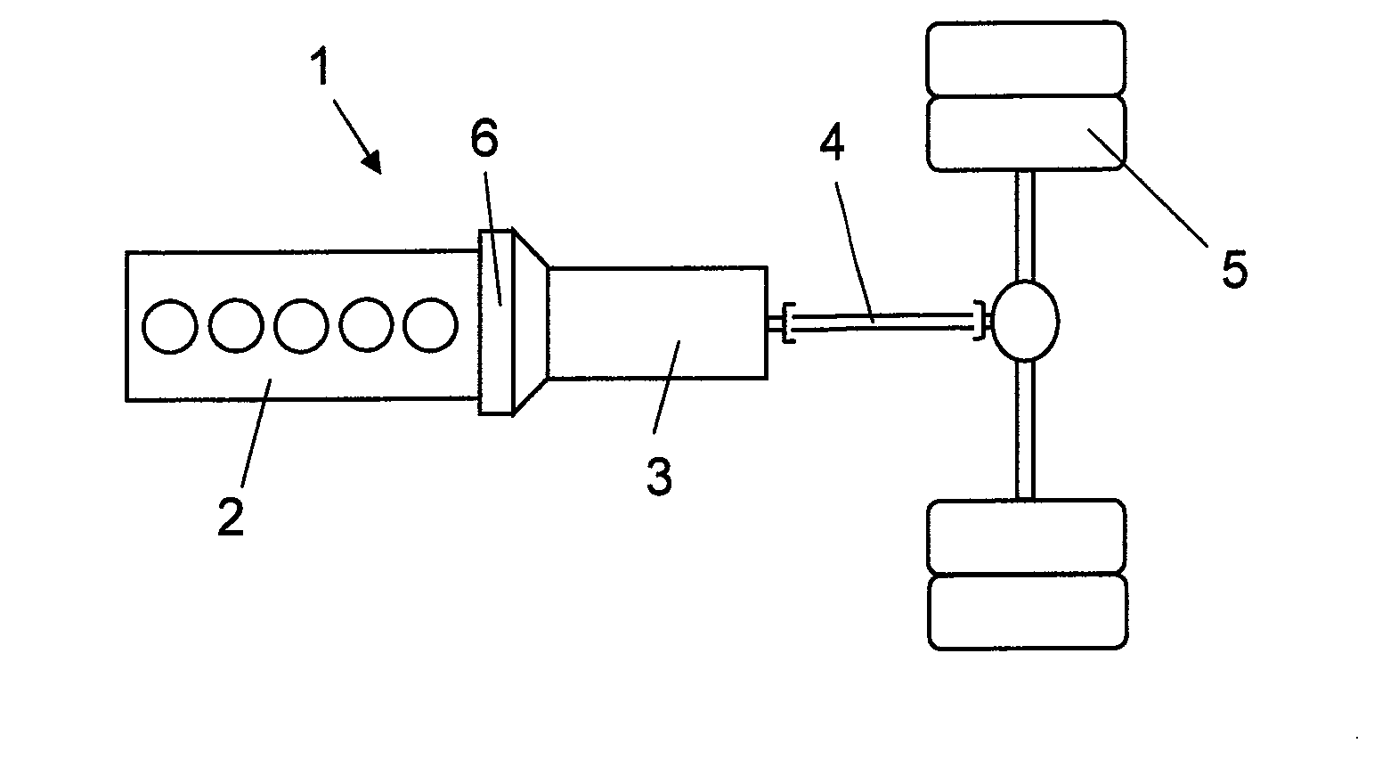
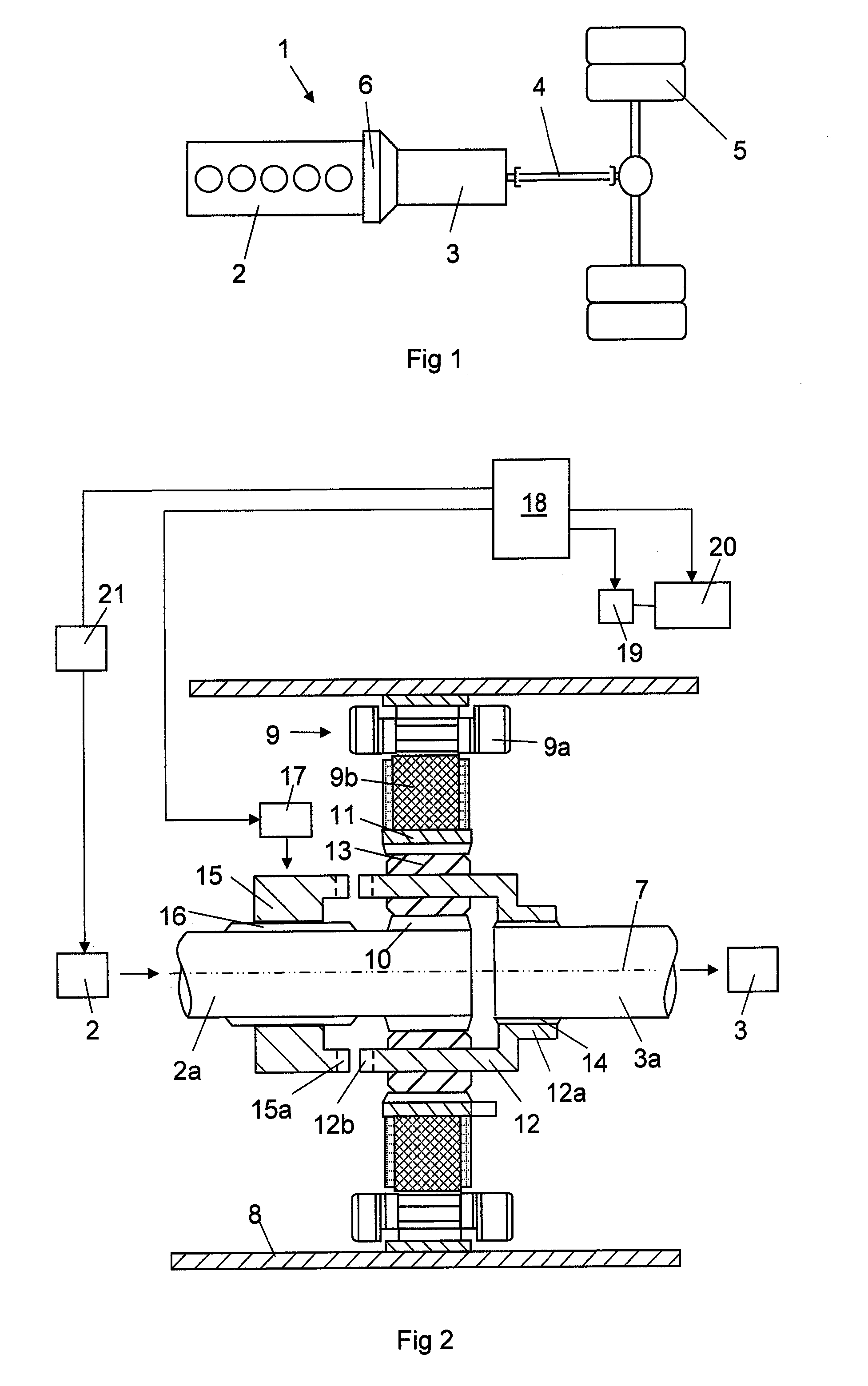
[0025]FIG. 1 shows a drivetrain for a heavy vehicle 1. The drivetrain comprises a combustion engine 2, a gearbox 3, a number of drive shafts 4 and drive wheels 5. The drivetrain has between the combustion engine 2 and the gearbox 3 an intermediate portion 6. FIG. 2 shows more detail of the components in the intermediate portion 6. The combustion engine 2 is provided with an output shaft 2a and the gearbox 3 with an input shaft 3a in the intermediate portion 6. The output shaft 2a of the combustion engine is arranged coaxially with respect to the input shaft 3a of the gearbox. The output shaft 2a of the combustion engine and the input shaft 3a of the gearbox are arranged to rotate around a rotation axis 7 in common. The intermediate portion 6 comprises a housing 8 enclosing an electric machine 9 and a planetary gear. The electric machine 9 comprises as usual a stator 9a and a rotor 9b. The stator 9a comprises a stator core secured in a suitable way on the inner side of the housing 8....


PUM


Abstract

A method for gearchange in a gearbox of a vehicle driving, said vehicle having a propulsion system comprising a combustion engine with an output shaft (2a), a gearbox (3) with an input shaft (3a), an electric machine (9) comprising a stator and a rotor, and a planetary gear comprising a sun gear (10), a ring gear (11) and a planet wheel carrier (12). The gearchange is carried out with the components of the planetary gear allowed to rotate with different rotational speeds and is finished by interlocking them. The combustion engine is controlled with respect to rotational speed during the gearchange towards the rotational speed required for the interlocking.

Description

CROSS-REFERENCE TO RELATED APPLICATIONS[0001]The present application is a 35 U.S.C. §§371 National Phase conversion of PCT / SE2013 / 050777, filed Jun. 26, 2013, which claims priority of Swedish Patent Application No. 1250720-8, filed Jun. 27, 2012, the contents of which are incorporated by reference herein. The PCT International Application was published in the English language.FIELD OF THE INVENTION AND PRIOR ART[0002]The present invention relates to a method for gearchange in a gearbox of a vehicle.[0003]The invention is especially but not exclusively directed to carrying out such a method for motor vehicles in the form of wheeled utility vehicles, especially heavy such vehicles, such as trucks and buses.[0004]Thus, the invention relates to method for gearchange in a hybrid vehicle, in which such a vehicle is generally a vehicle which may be driven by a primary engine, here a combustion engine, and a secondary engine, here an electric machine. The electric machine is suitably provid...

Claims


Application Information

Patent Timeline
IPC IPC(8): B60W20/00B60W10/11B60W10/06B60W10/08B60W30/19F16H61/04
CPCB60W20/108B60W30/19F16H61/0403Y10S903/93B60W10/08B60W10/11F16H2061/0422B60W10/06B60K6/365B60W20/00F16H61/04B60W10/02B60Y2400/421B60Y2300/72B60Y2200/92F16H2306/46F16H2306/48F16H2306/50B60W20/15Y02T10/62F16H2306/40
Inventor PETTERSSON, NIKLASBERGQUIST, MIKAELLINDSTROM, JOHANKJELL, ANDERSBJORKMAN, MATHIAS
Owner SCANIA CV AB
Why Eureka
Try Eureka