
Sheet feeding unit and electrophotographic image forming apparatus

a technology of electrophotographic image and feeding unit, which is applied in the direction of electrographic process, instruments, transportation and packaging, etc., can solve the problems of inability to reliably feed the sheet using a stably controlled feed method, increase the size and cost of the sheet feeding unit, and achieve high reliability in separating and feeding sheets, reducing the charging pitch, and reducing the charge pitch

Inactive Publication Date: 2015-07-23
RICOH KK
View PDF3 Cites 3 Cited by
  • Summary
  • Abstract
  • Description
  • Claims
  • Application Information

AI Technical Summary

Benefits of technology

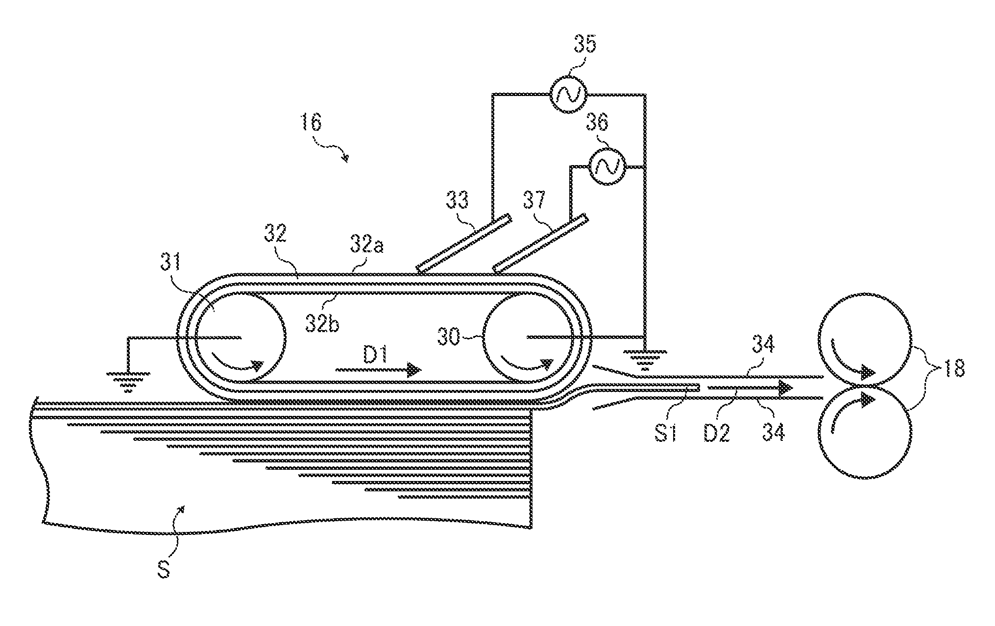
Example embodiments describe a sheet feeding unit that can handle various types of sheets stably, regardless of changes in environmental conditions, and reliably separate and feed sheets quickly and robustly. This allows for a smaller charging pitch and improved feeding performance.

Problems solved by technology

One problem with such an arrangement using the friction feed method is that, although a configuration of the sheet feeding unit can be simplified, the pick-up member may need to be pressed against the surface of an uppermost sheet with a biasing member such as a spring or the like to obtain a large frictional force.
Because the coefficient of friction at the surface of the pick-up member having a larger coefficient of friction such as rubber may deteriorate over time and according to environmental factors, the friction feed method cannot stably provide a higher ability to reliably feed the sheet.
With recording media having a substantially small coefficient of friction, sheets providing friction varying depending on temperature, or sheets absorbing moisture and adhering to each other, the pickup-up member of the sheet feeding unit may not separate the uppermost sheet from other sheets properly with only the friction feed method.
However, although providing a more reliable ability to feed the recording media compared to the friction feed method, the air suction method may be noisy and cause an increase in size and costs of the sheet feeding unit.
Consequently, the air suction method is not practical for image forming apparatuses installed in an office or the like.
However, this sheet separation method may also be noisy and cause an increase in size and costs of the sheet feeding unit.
Conversely, when a sufficient force of attraction cannot be obtained, sheets cannot be fed and conveyed properly.
If the endless belt member is rotated in the sheet conveyance direction while the force of attraction is still exerted on the plurality of sheets, two or more sheets are fed mistakenly, and proper sheet feeding cannot be performed reliably.
However, in Technique 1, the necessity of measurement of the physical property of a target sheet after separation from a stack of sheets makes it impossible to control for the first sheet.
Further, the technique is inapplicable where sheets having different physical properties are accommodated in the same cassette.
This makes it difficult for the blocking member to reliably separate the uppermost sheet from these sheets, considering a wide range of conditions.
Further, Technique 3 requires a substantially long contact period of time, and it is likely to decrease productivity of the sheet feeding unit, resulting in lack of merchantability.
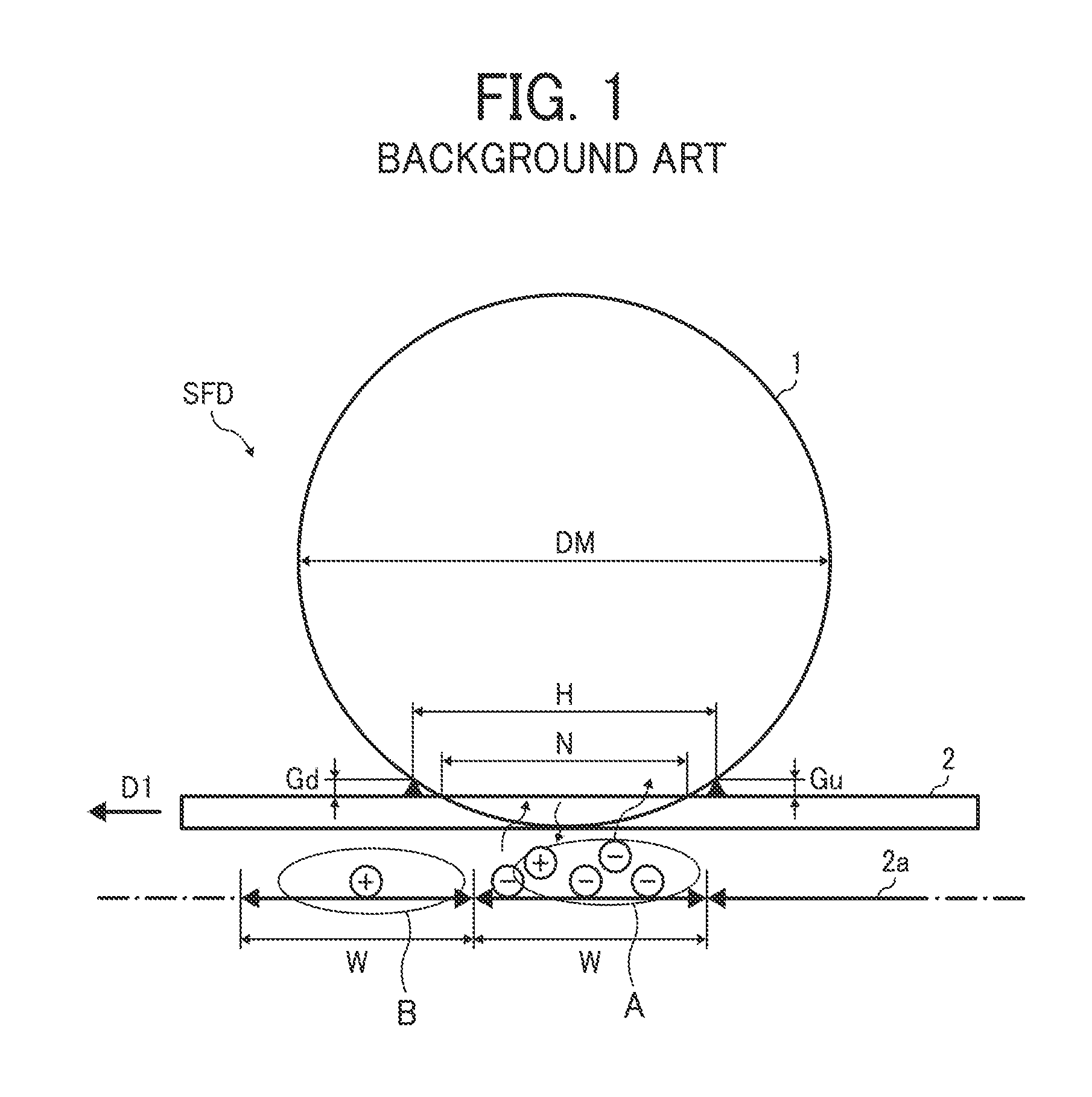
However, if a charging roller is used as a charging electrode to charge the surface of the endless belt member, the intervals or charging pitches between the alternating charges including positive charge and negative charge cannot be decreased, which is disadvantageous for the following reason.
As a result, minute alternating charges cannot be provided, which cannot obtain the necessary force of attraction for attracting the sheets onto the endless belt member 2.

Method used


Image

  • Sheet feeding unit and electrophotographic image forming apparatus
  • Sheet feeding unit and electrophotographic image forming apparatus
  • Sheet feeding unit and electrophotographic image forming apparatus

Examples


Embodiment Construction

[0062]It will be understood that if an element or layer is referred to as being “on”, “against”, “connected to” or “coupled to” another element or layer, then it can be directly on, against, connected or coupled to the other element or layer, or intervening elements or layers may be present. In contrast, if an element is referred to as being “directly on”, “directly connected to” or “directly coupled to” another element or layer, then there are no intervening elements or layers present. Like numbers referred to like elements throughout. As used herein, the term “and / or” includes any and all combinations of one or more of the associated listed items.

[0063]Spatially relative terms, such as “beneath”, “below”, “lower”, “above”, “upper” and the like may be used herein for ease of description to describe one element or feature's relationship to another element(s) or feature(s) as illustrated in the figures. It will be understood that the spatially relative terms are intended to encompass...


PUM


Abstract

A sheet feeding unit that can be incorporated in an image forming apparatus includes an endless belt and a charging member. The charging member may charge the endless belt with an alternating voltage to attract a sheet to separate from multiple sheets and feed the sheet, and may have an electrode contacting the endless belt at an angle thereto and between which a nip is formed. The endless belt and an interior surface of the charging member may define a space across which electric discharge is performed to charge an outer layer of the endless belt. A distance of the gap and a length of the nip in the sheet conveyance direction may define a basic charging region. The distance of the basic charging region may be smaller than a distance of a unit charging region where the electric charge of identical polarity is held on the endless belt.

Description

[0001]This application is a continuing application of and claims priority under 35 U.S.C. §120 / 121 to U.S. application Ser. No. 12 / 801,015, filed May 17, 2010, which claims priority to 35 U.S.C. §119 from Japanese Patent Application No. 2009-121544, filed on May 20, 2009 in the Japan Patent Office, and Japanese Patent Application No. 2010-106429, filed on May 6, 2010 in the Japan Patent Office, which are hereby incorporated by reference herein in their entirety.BACKGROUND[0002]1. Field[0003]Exemplary embodiments of the present patent application relate to a sheet feeding unit and an electrophotographic image forming apparatus incorporating the sheet feeding unit, and more particularly, to a sheet feeding unit that electrostatically attracts a sheet of a recording medium to an endless belt member for separating and feeding the sheet therefrom, and an electrophotographic image forming apparatus including the sheet feeding unit.[0004]2. Related Art[0005]Related-art image forming appara...

Claims


Application Information

Patent Timeline
Patent Type & Authority Applications(United States)
IPC IPC(8): B65H3/18B65H3/06B65H5/06B41J11/00B65H5/00
CPCB65H3/18B41J11/007B65H3/0669B65H5/06B65H5/004G03G15/6511G03G2215/00396
Inventor HIGAKI, HIDETO
Owner RICOH KK
Learn More