
Quantum logic

a logic and quantum technology, applied in the field of quantum logic, can solve the problems of compromising the readout process, achieving control, and exceeding stringent requirements

Active Publication Date: 2015-07-23
NEWSOUTH INNOVATIONS PTY LTD
View PDF4 Cites 4 Cited by
  • Summary
  • Abstract
  • Description
  • Claims
  • Application Information

AI Technical Summary

Benefits of technology

The patent describes a device for performing quantum logic using a device called a quantum computer. The quantum computer has a physical system with a qubit, which is the quantum state of the spin of an electron bound to a donor atom. The qubit can be read, and its state can be controlled by a process called quantum logic. The patent also describes a method for detecting the interaction between two qubits using a controllable exchange interaction. The technical effects of the patent include the ability to perform quantum logic using a scalable quantum computer, and the development of a method for controlling the interaction between qubits.

Problems solved by technology

If the spin state changes while “waiting” for the tunnelling event to occur on the time scale τt, then the readout process is compromised.
A difficulty with achieving control of the exchange interaction between donors and the observation of exchange oscillations arises for the structure shown in FIG. 3(a), by the need to reconcile the exchange oscillation timescale τJ with the spin readout and tunnelling timescale τt.
This is an extremely stringent requirement, which is not likely to be implemented soon.
In addition, the requirements on lithography, alignment and nanofabrication to place an electrostatic gate 303 in between two donors are extremely demanding.
However, the dynamic range of J obtained like this is still not likely to reach the required 5 orders of magnitude mentioned above.

Method used


Image

  • Quantum logic
  • Quantum logic
  • Quantum logic

Examples


Embodiment Construction

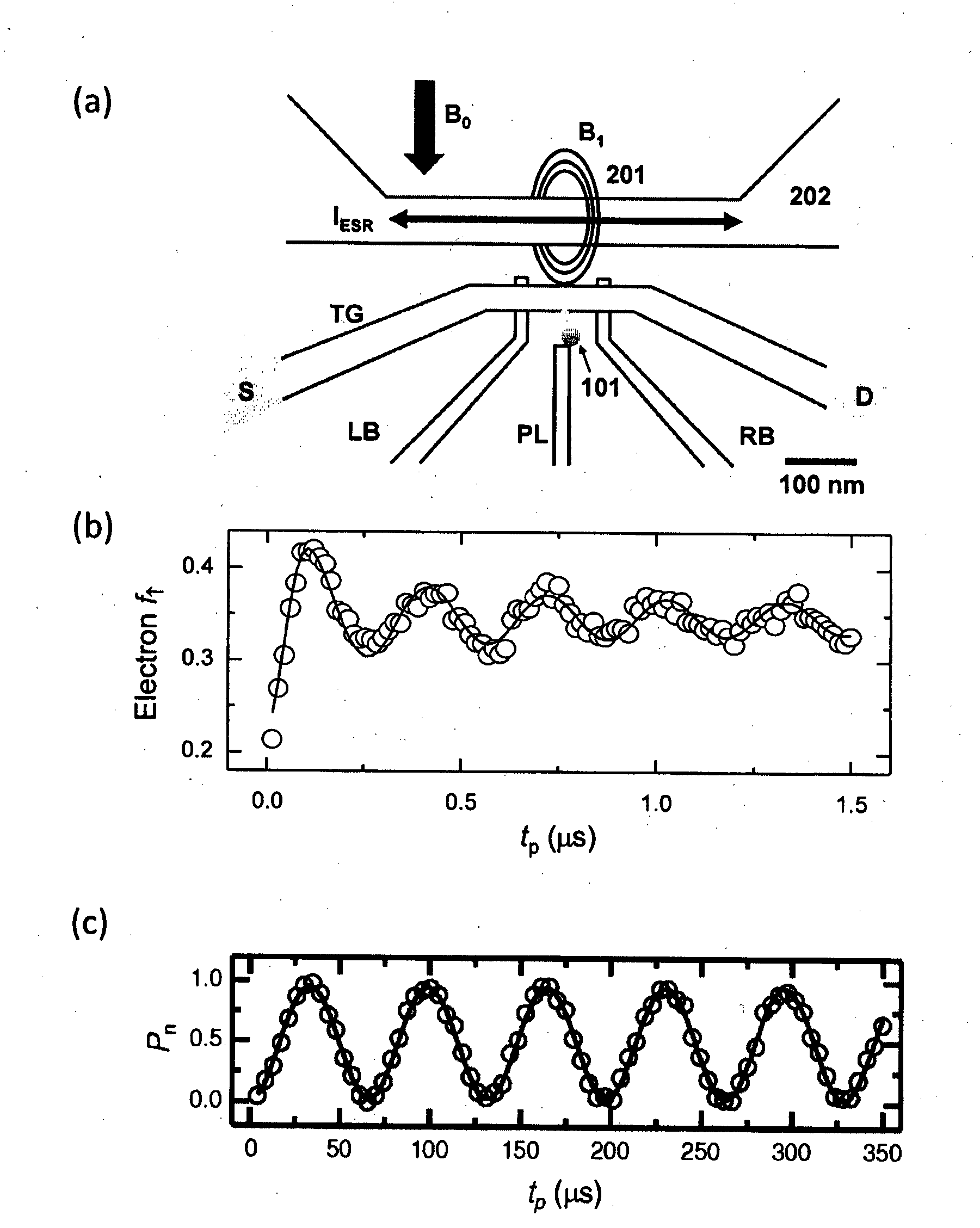
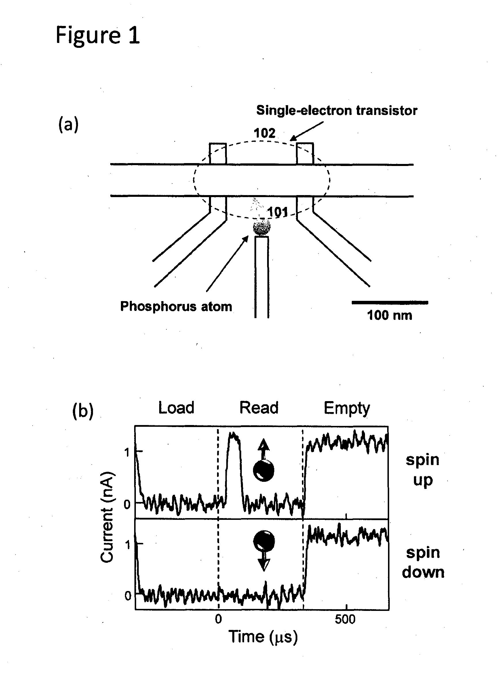
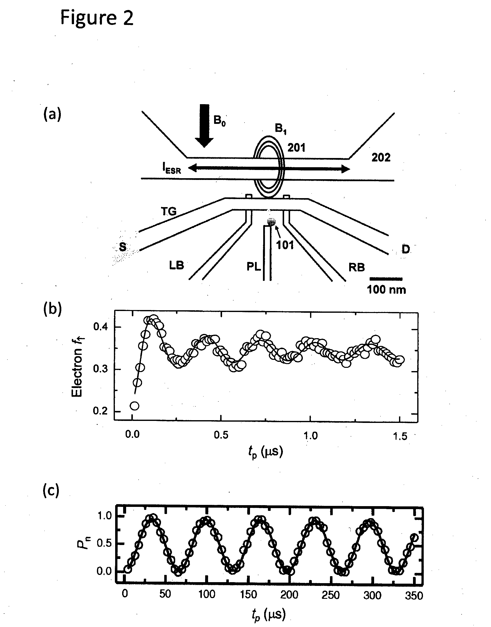
[0074]Referring first to FIG. 5(a), the device for performing quantum logic, includes a spin readout device 504, placed in proximity to two donors 301, 302. The distance between donors and spin readout device 504 is such that quantum tunnelling of an electron is possible between each of the donors 301 and 302 and the spin readout device 504. Referring now to FIG. 5(b) the spin readout device 504 comprises an electron reservoir 505 (for instance the island of a single-electron transistor, or a 2-dimensional electron gas), whose Fermi level EF 506 will determine the electrochemical potential at which the donor electron becomes readable.

[0075]The electrochemical potential of the donors is controlled by the voltage VD1 on the electrostatic gate 501 (for the left donor 301) and VD2 on gate 502 (for the right donor 302). If VD1≠VD2 an electric field Eε exists between the donors. This leads to a detuning e 503 between the electrochemical potentials of the two donors. As shown in FIG. 3(c),...


PUM


Abstract

This invention concerns a method to switch on and off the exchange interaction J between electron spins bound to donor atoms. The electron spins have the role of ‘qubits’ to carry quantum information, and the exchange interaction J has the role of mediator for two-qubit quantum logic operations. The invention aims at exploiting the existence of a further magnetic interaction, the hyperfine interaction A, between each electron spin and the nuclear spin of the donor atom (301, 302) that binds the electron. The hyperfine interaction A, together with the ability to read out (504) and control the state of the nuclear spins, is used to suppress the effect of the exchange interaction J at all times, except while a quantum logic operation is being performed. In this way, the result of the quantum logic operation is not distorted after the operation has taken place. In a further aspect, the invention concerns an electronic device where the method can be practically implemented, and a large scale device made up of many of the devices.

Description

CROSS-REFERENCE TO RELATED APPLICATIONS[0001]The present application claims priority from Australian Provisional Patent Application No 2012903473 filed on 13 Aug. 2012, the content of which is incorporated herein by reference.TECHNICAL FIELD[0002]This disclosure concerns quantum logic, in particular a device for performing quantum logic, a method for performing quantum logic and for controlling the exchange interaction between electron spins of a pair of donor electrons.BACKGROUND ART[0003]A scalable quantum computer could be constructed where quantum information is encoded in the spin of electrons bound to donor atoms in silicon, as described in Ref.[0004][1]. The operation of such a quantum computer involves at least four fundamental steps:[0005]1. The definition and isolation of a physical system that carries the quantum information, which is called a “qubit”;[0006]2. The readout of the state of the qubit;[0007]3. The encoding of quantum information on the qubit, that is a ‘write...

Claims


Application Information

Patent Timeline
IPC IPC(8): G06N99/00
CPCG06N99/002B82Y10/00G01R33/44G01R33/60G06N10/00
Inventor MORELLO, ANDREAKALRA, RACHPONLAUCHT, ARNE
Owner NEWSOUTH INNOVATIONS PTY LTD
Learn More