Method and system for advanced electronic border security

a technology of electronic border protection and fiberoptic cable, applied in the field of advanced electronic border protection using buried fiberoptic cables, can solve the problems of inability to install and maintain remote electric power generators, inability to provide reliable monitoring equipment and sensors, etc., to achieve high reliability, low maintenance, and cost-effective

Active Publication Date: 2015-07-23
WEINSTEIN BRADLEY A +1
View PDF5 Cites 8 Cited by
  • Summary
  • Abstract
  • Description
  • Claims
  • Application Information

AI Technical Summary

Benefits of technology

[0013]The method and system provide a cost effective border protection system which is highly sensitive and reliable in detecting border incursions and reporting such incursions to a monitoring site or sites. As such, the need for installing and maintaining electrical generators and related equipment at sites intermediate the respective ends of the border is eliminated.
[0014]The system...

Problems solved by technology

One of the challenges in protecting borders is that borders usually involve long distances, covering a wide variety of terrains (flat, rolling, mountainous, sandy, packed earth, rocky, forested, water, swampy or marshy, etc.).
Further, much, if not most, of a border usually stretches through remote and uninhabited areas.
As a consequence, available electric utility service, installation of above ground monitoring eq...

Method used


Image

  • Method and system for advanced electronic border security
  • Method and system for advanced electronic border security
  • Method and system for advanced electronic border security

Examples


Embodiment Construction

[0023]The following detailed description illustrates the invention by way of example and not by way of limitation. This description clearly enables one skilled in the art to make and use the invention, and describes several embodiments, adaptations, variations, alternatives and uses of the invention, including what is presently believed to be the best mode of carrying out the invention. Additionally, it is to be understood that the invention is not limited in its application to the details of construction and the arrangement of components set forth in the following description or illustrated in the drawings. The invention is capable of other embodiments and of being practiced or carried out in various ways. Also, it will be understood that the phraseology and terminology used herein is for the purpose of description and should not be regarded as limiting.

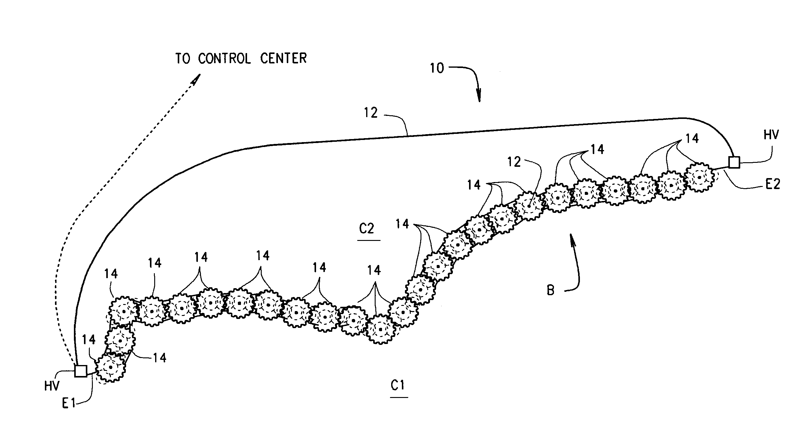
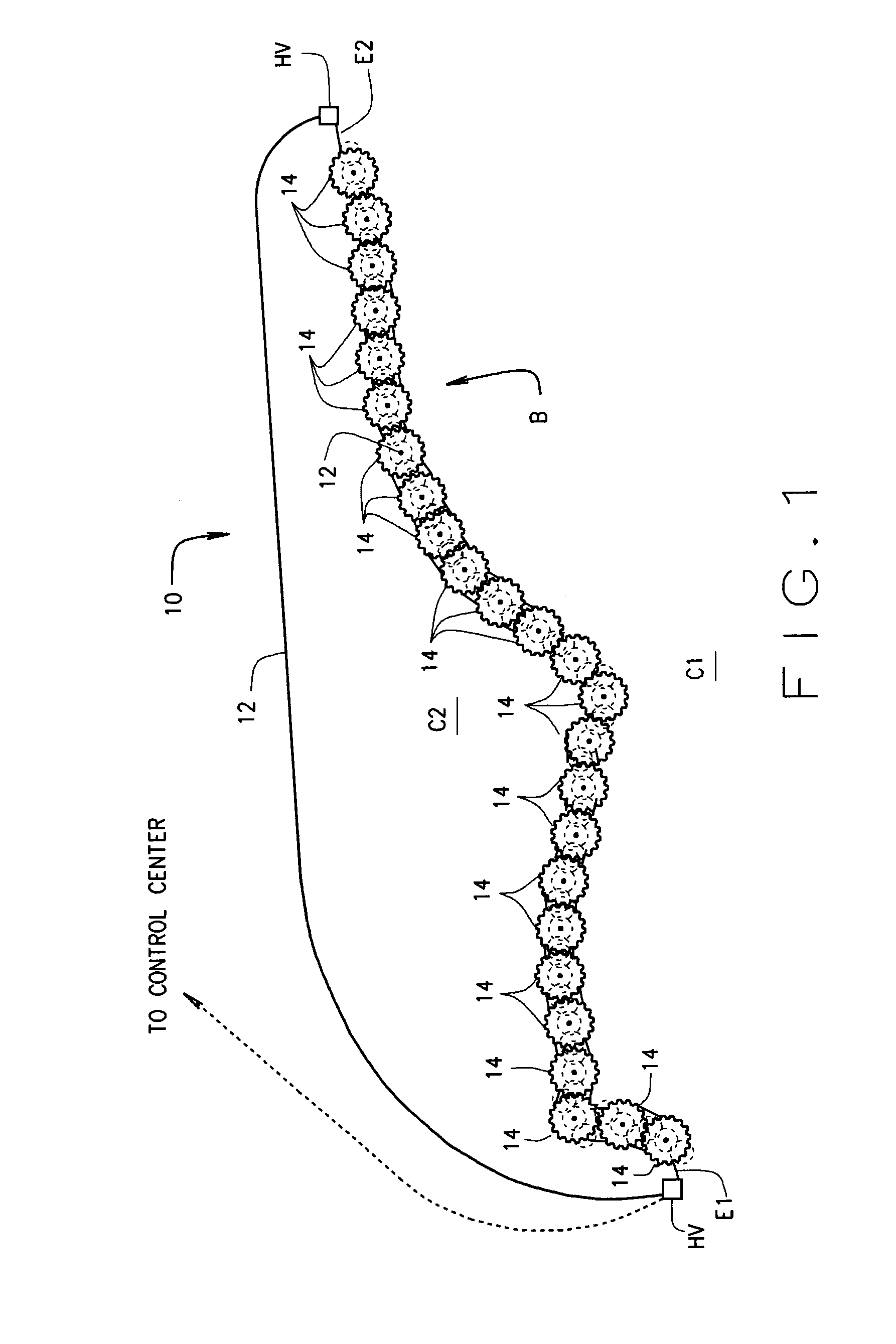
[0024]Referring to the drawings, a border B extends between two countries C1 and C2. Although not shown in the drawings, border B ...


PUM


Abstract

A system (10) for protecting a border (B) comprises a fiber-optic cable (12) extending from one end of a border to the other end thereof. The cable includes a bundle of optical fibers which connect to sensors placed at intervals long the border. Included within the fiber-optic cable is a high voltage conductor by which high voltage AC is introduced into, and passes through, the cable for powering the sensors. The high voltage is stepped down and rectified from AC to DC for this purpose. Various types of sensors (100-700) are arranged in pods (14) located at intervals along the length of the border. A method of border protection is also disclosed.

Description

REFERENCE TO RELATED APPLICATIONS[0001]This application is based upon and claims the benefit of U.S. provisional patent application 61 / 694,853 filed Aug. 30, 2012.STATEMENT REGARDING FEDERALLY SPONSORED RESEARCH OR DEVELOPMENT[0002]N / ABACKGROUND OF THE INVENTION[0003]This invention relates to border protection between two countries or bounded areas; and, more particularly, to a method and system for advanced electronic border protection using a buried fiber-optic cable in which high voltage conductors are enclosed within the same cable sheath. This allows electrical power to be supplied throughout the length of the border without requiring power sources located at intermediate points along the length of the border.[0004]One of the challenges in protecting borders is that borders usually involve long distances, covering a wide variety of terrains (flat, rolling, mountainous, sandy, packed earth, rocky, forested, water, swampy or marshy, etc.). Further, much, if not most, of a border ...

Claims


Application Information

Patent Timeline
IPC IPC(8): G08B13/24
CPCG08B13/2497G08B13/186
Inventor WEINSTEIN, RICHARD D.
Owner WEINSTEIN BRADLEY A
Why Eureka
Try Eureka