
Power-Cell Switching-Cycle Capacitor Voltage Control for Modular Multi-Level Converters

a technology of switching-cycle capacitors and converters, applied in the field of modular power converters, can solve the problems of limiting the potential power density of the converter modules, reducing the size or value of the capacitor, and stressing the switches of the modules, so as to reduce the capacitor value and size requirements

Active Publication Date: 2015-07-23
VIRGINIA TECH INTPROP INC
View PDF6 Cites 26 Cited by
  • Summary
  • Abstract
  • Description
  • Claims
  • Application Information

AI Technical Summary

Benefits of technology

This is a new way to control power converters that can reduce the size of capacitors needed and work at low frequencies, including DC operation. This makes it easier to design and use the converters for different uses, and may make them more efficient.

Problems solved by technology

This latter fact is a major issue for AC motor starting where the frequency must increase from zero Hz, especially where high starting torque is required.
However, such an approach increases stress on the switches of the modules and requires converters to be de-rated for low frequency operation while no reduction in capacitor size or value is achieved; limiting the potential power density of the converter modules.

Method used


Image

  • Power-Cell Switching-Cycle Capacitor Voltage Control for Modular Multi-Level Converters
  • Power-Cell Switching-Cycle Capacitor Voltage Control for Modular Multi-Level Converters
  • Power-Cell Switching-Cycle Capacitor Voltage Control for Modular Multi-Level Converters

Examples


Embodiment Construction

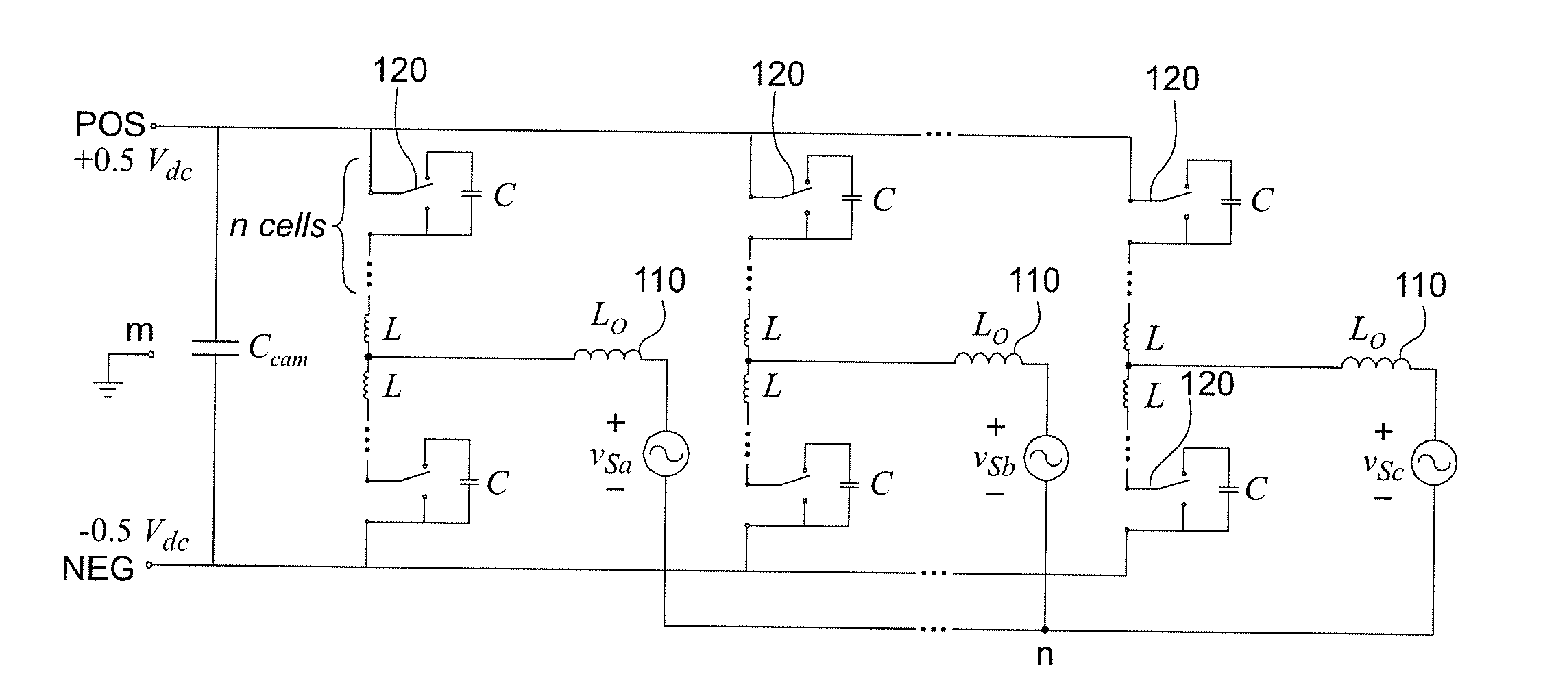
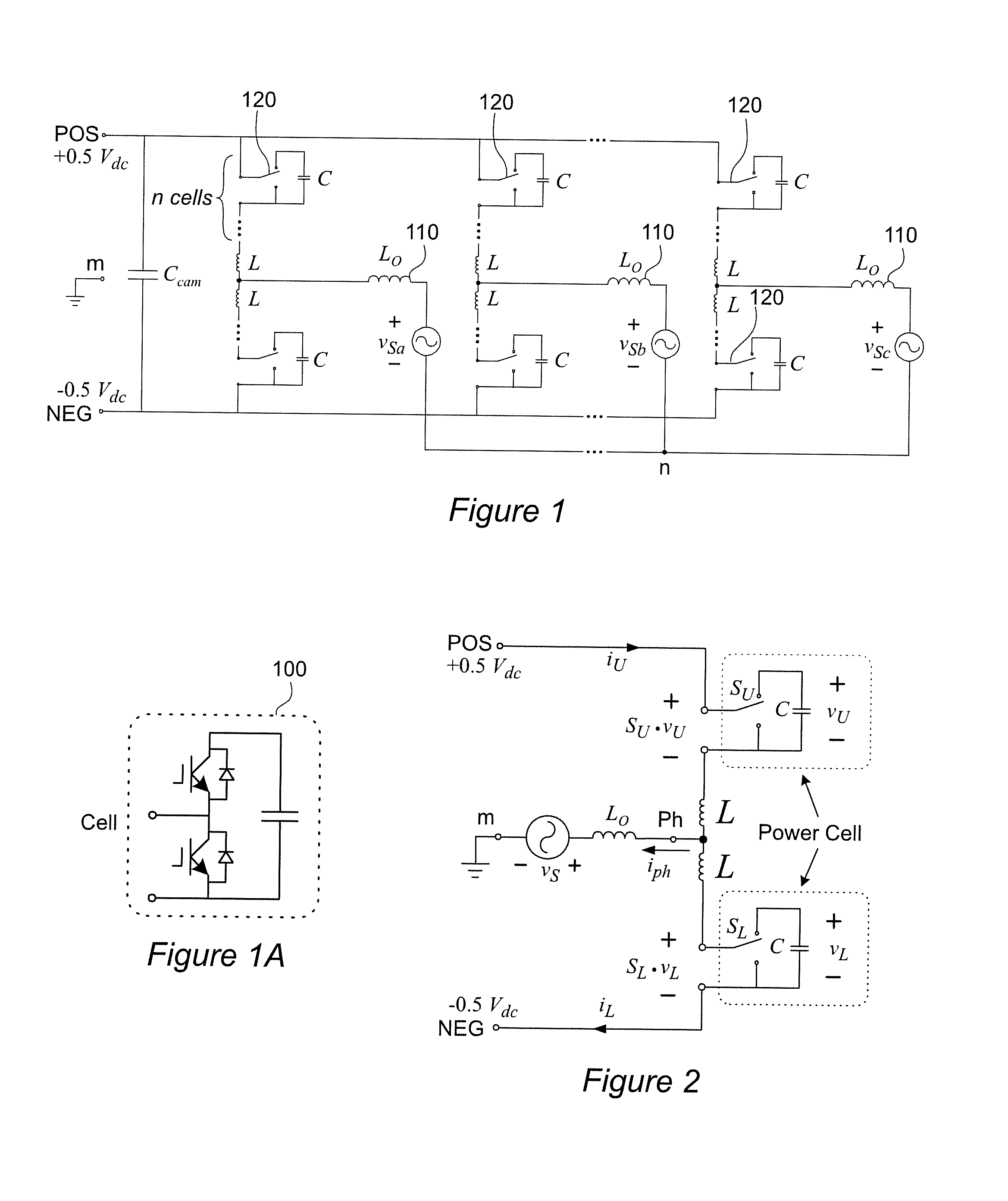
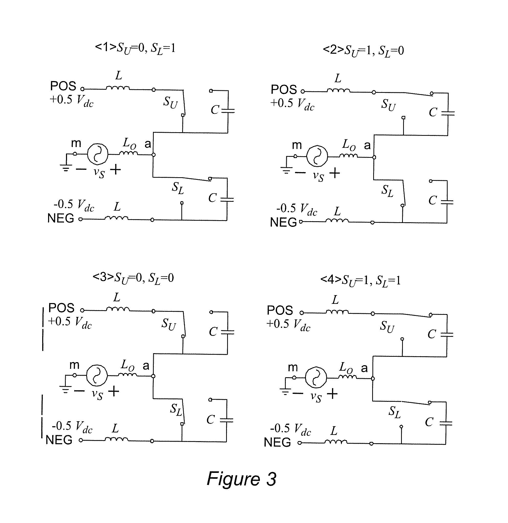
[0032]Referring now to the drawings, and more particularly to FIG. 1, there is shown a generalized schematic diagram of a modular multi-level converter (MMC) to which the invention may be advantageously applied. While the basic architecture of the MMC illustrated in FIG. 1 is known, at the level of detail provided by FIG. 1, the invention may or may not be included since an embodiment including the invention would principally differ from known embodiments by having smaller capacitor and inductor values and sizes for a given ripple specification and different switching control which is only generically depicted in FIG. 1. It should also be noted that in most widely used known MMCs, the common DC capacitor, Ccom, is not necessary and not shown. However, in the switching cycle capacitor voltage control (SCCVC) of the present invention this capacitor is required to absorb switching frequency currents as will be understood from the following discussion although this capacitor may be omit...


PUM


Abstract

In a modular multi-level power converter, additional switching states are interleaved between main switching states that control output voltage or waveform. The additional switching states provide current from a DC-link to charge capacitors in respective modules or cells to an offset voltage from which the capacitor voltages are controlled toward a reference voltage during each switching cycle rather than being allowed to build up over a period of an output waveform of variable line frequency, possibly including zero frequency. Since the switching cycle is much shorter than the duration of a line frequency cycle and the capacitor voltages are balanced during each switching cycle, output voltage ripple can be limited as desired with a capacitor of much smaller value and size than would otherwise be required.

Description

CROSS-REFERENCE TO RELATED APPLICATIONS[0001]This application claims benefit of priority of U.S. Provisional Applications 61 / 927,514, filed Jan. 15, 2014 and 62 / 027,551, filed Jul. 22, 2014, both of which are hereby incorporated by reference in their entireties.FIELD OF THE INVENTION[0002]The present invention generally relates to modular power converters, including modular multi-level converters (MMCs) and, more particularly, a switching-cycle capacitor voltage control (SCCVC) therefor to reduce required capacitor size and value and increase power density.BACKGROUND OF THE INVENTION[0003]Although most electronic devices operate from power supplied at a more-or-less constant voltage (referred to as direct current or DC), many devices presenting larger loads such as appliances or other devices having motors or heating elements are designed to operate on power supplied at a sinusoidally varying voltage (referred to as alternation current or AC). In most of the world, power is generate...

Claims


Application Information

Patent Timeline
IPC IPC(8): H02M7/797
CPCH02M7/797H02M7/483H02M1/0003H02M7/4835
Inventor WANG, JUNBURGOS, ROLANDOBOROYEVICH, DUSHANWEN, BO
Owner VIRGINIA TECH INTPROP INC
Learn More