
Flexographic printing system with solvent replenishment

a flexographic printing and solvent technology, applied in the field of flexographic printing, can solve the problems of extending the limits of flexographic printing technology, ghosting, misplaced location sensing, etc., and achieve the effects of reducing the variability of line widths of printed linear features, reducing the performance of flexographic printing systems, and increasing the robustness of device fabrication processes

Active Publication Date: 2015-07-30
EASTMAN KODAK CO
View PDF3 Cites 6 Cited by
  • Summary
  • Abstract
  • Description
  • Claims
  • Application Information

AI Technical Summary

Benefits of technology

This patent aims to improve the performance and consistency of flexographic printing systems by controlling the viscosity of the ink. By analyzing and adjusting the features of printed patterns, the system can achieve more robust and consistent performance during device fabrication. Additionally, a distribution tube is used to supply replenished ink across the width of the ink reservoir, resulting in a more uniform distribution and improved viscosity consistency. Overall, the patent aims to optimize the flexographic printing process for better efficiency and reliability.

Problems solved by technology

As the human body is also an electrical conductor, touching the surface of the screen results in a distortion of the screen's electrostatic field, measurable as a change in capacitance.
This method produces a stronger signal than mutual capacitance, but it is unable to resolve accurately more than one finger, which results in “ghosting”, or misplaced location sensing.
Printing such narrow lines stretches the limits of flexographic printing technology, especially when relatively high viscosity printing inks are used.
In particular, it has been found to be difficult to achieve a desired tolerance of plus or minus one micron in line width tolerance.

Method used


Image

  • Flexographic printing system with solvent replenishment
  • Flexographic printing system with solvent replenishment
  • Flexographic printing system with solvent replenishment

Examples


Embodiment Construction

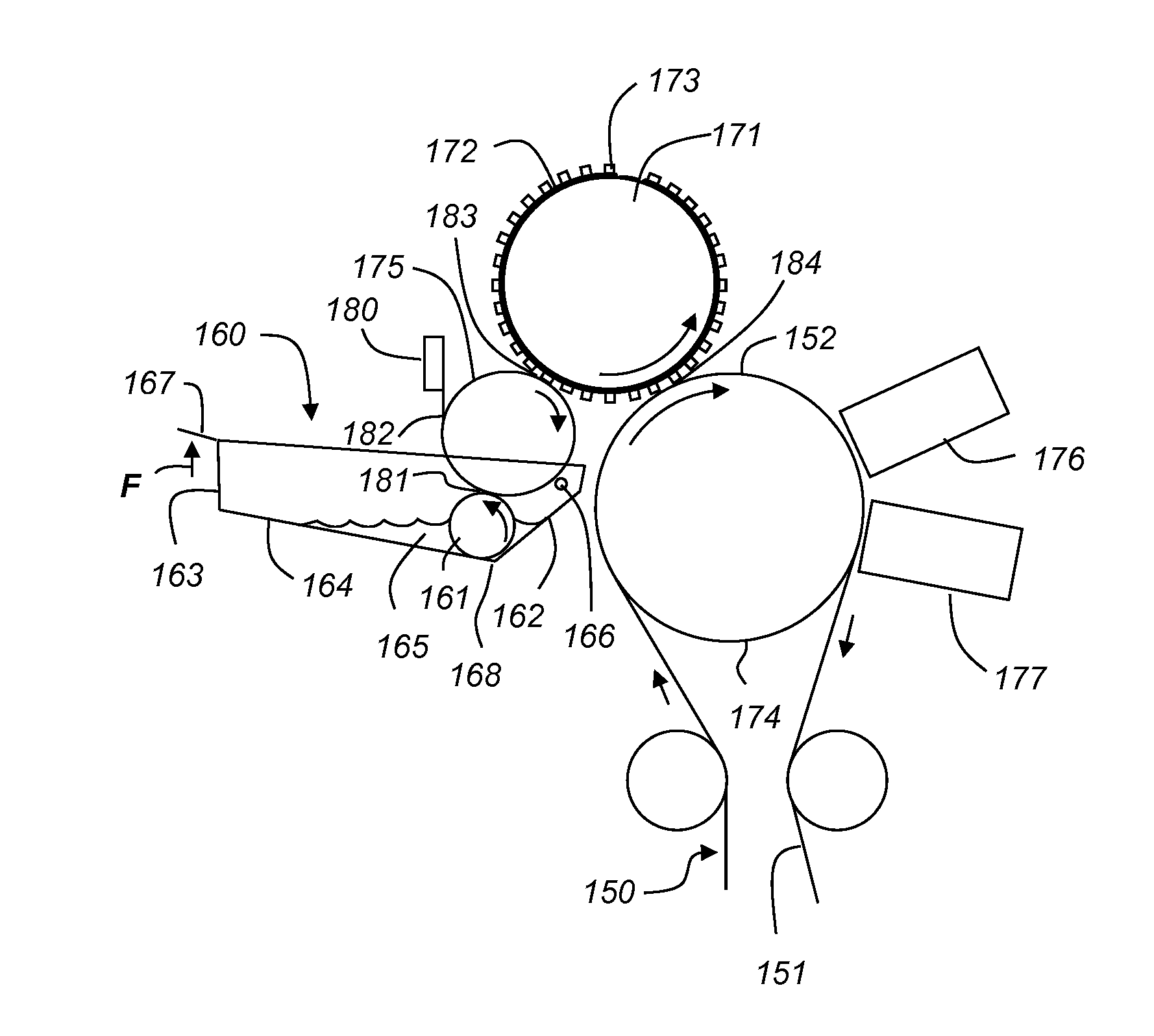
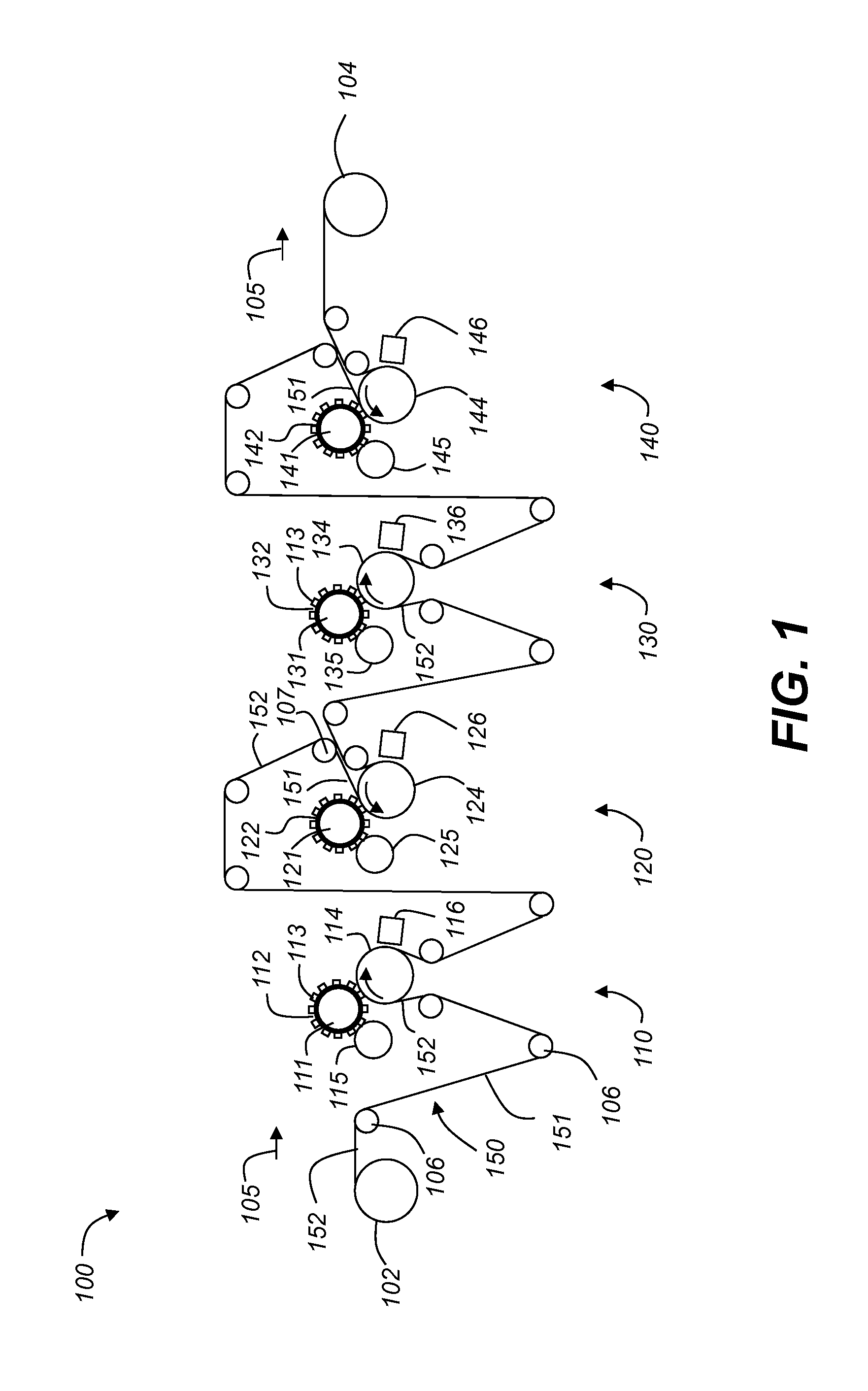
[0042]The present description will be directed in particular to elements forming part of, or cooperating more directly with, an apparatus in accordance with the present invention. It is to be understood that elements not specifically shown, labeled, or described can take various forms well known to those skilled in the art. In the following description and drawings, identical reference numerals have been used, where possible, to designate identical elements. It is to be understood that elements and components can be referred to in singular or plural form, as appropriate, without limiting the scope of the invention.

[0043]The invention is inclusive of combinations of the embodiments described herein. References to “a particular embodiment” and the like refer to features that are present in at least one embodiment of the invention. Separate references to “an embodiment” or “particular embodiments” or the like do not necessarily refer to the same embodiment or embodiments; however, such...


PUM

PropertyMeasurementUnit
viscosityaaaaaaaaaa
viscosityaaaaaaaaaa
widthaaaaaaaaaa

Abstract

A flexographic printing system uses a flexographic printing plate to produce printed patterns on a substrate. An ink recirculation system is used to reduce variability in system performance resulting from ink viscosity changes. A recirculation pump moves ink through an ink recirculation line connected to an ink reservoir. A metering pump adds a controlled flow rate of solvent from a solvent replenishment chamber into the ink recirculation line, thereby providing replenished ink. The replenished ink is returned to the ink reservoir through a distribution tube that includes a plurality of supply ports at a plurality of spaced apart locations across a width of the ink reservoir. A control system is used to control the flow rate of solvent provided by the metering pump.

Description

CROSS REFERENCE TO RELATED APPLICATIONS[0001]Reference is made to commonly-assigned, co-pending U.S. patent application Ser. No. ______ (Docket K001695), entitled “Flexographic printing system providing controlled feature characteristics” by James Shifley et al.; and to commonly-assigned, co-pending U.S. patent application Ser. No. ______ (DOCKET K001704), entitled “Controlling line widths in flexographic printing” by James Shifley et al., each of which is herein incorporated by reference.FIELD OF THE INVENTION[0002]This invention pertains to the field of flexographic printing, and more particularly to a solvent replenishment system for controlling the viscosity of ink provided to a flexographic printing plate.BACKGROUND OF THE INVENTION[0003]Flexography is a method of printing or pattern formation that is commonly used for high-volume printing runs. It is typically employed for printing on a variety of soft or easily deformed materials including, but not limited to, paper, paperboa...

Claims


Application Information

Patent Timeline
Patent Type & Authority Applications(United States)
IPC IPC(8): B41F31/13B41F5/24
CPCB41F5/24B41F31/13B41F31/005B41F31/027Y10T428/24802B41F33/0045
Inventor SHIFLEY, JAMES DOUGLASALEXANDROVICH, PETER STEVENRECZEK, JAMES ALBERT
Owner EASTMAN KODAK CO
Learn More