Laser scanning head-up display system for vehicles

a head-up display and laser scanning technology, applied in the field of head-up displays, can solve the problems of unwanted brightness differences, so-called speckles, in the displayed image, and achieve the effect of improving display quality

Inactive Publication Date: 2015-07-30
DZHONSON KONTROLZ GMBKH
View PDF1 Cites 31 Cited by
  • Summary
  • Abstract
  • Description
  • Claims
  • Application Information

AI Technical Summary

Benefits of technology

[0005]It was therefore the object of the present invention to provide a head-up display which does not have the disadvantages of the prior art and e

Problems solved by technology

However, the use of lasers is disadvantageous in that there are unwanted bright

Method used


Image

  • Laser scanning head-up display system for vehicles
  • Laser scanning head-up display system for vehicles
  • Laser scanning head-up display system for vehicles

Examples


Embodiment Construction

[0022]In the various figures, equivalent parts are always provided with the same reference signs and are also therefore, in general, respectively only named or mentioned once.

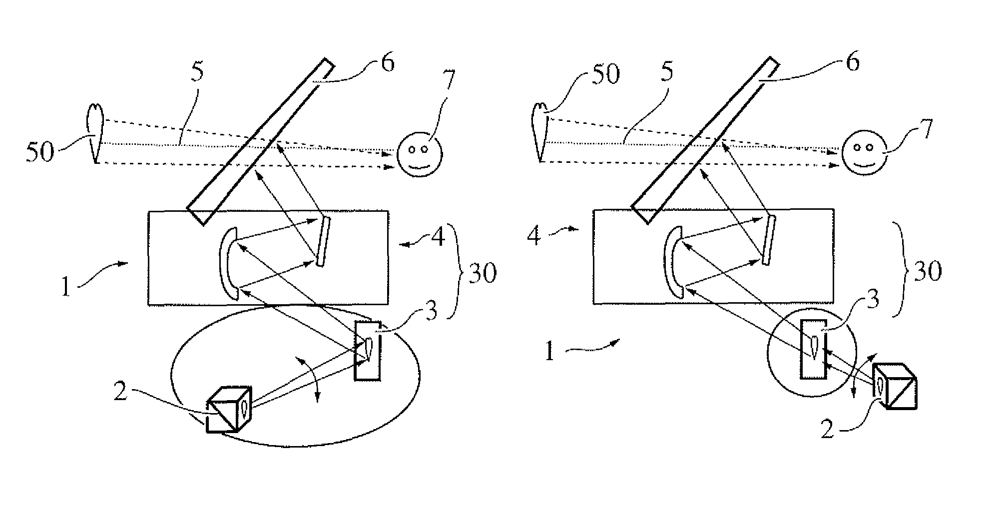
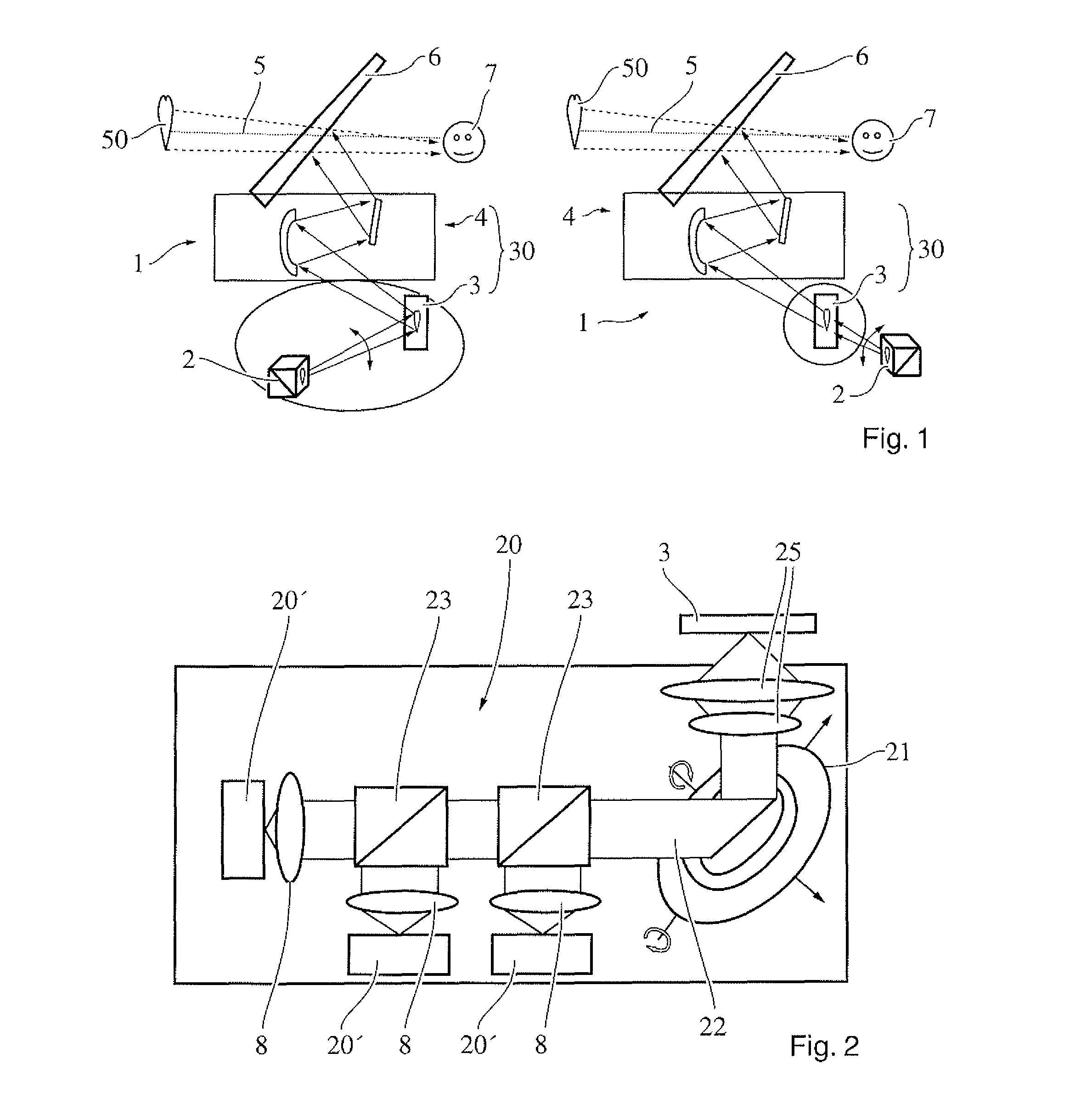
[0023]FIG. 1 depicts two possible head-up displays 1 according to the invention. The two head-up displays 1 are substantially identical, with the left-hand head-up display 1 being of the so-called reflection type and the right-hand head-up display 1 being of the so-called transmission type. With reference to the left-hand representation, a picture to be displayed is built up point-by-point from individual laser spots by means of a laser 20 and a corresponding mechanism 2, projected onto a projection plane 3 and reflected there. This image reflected by the projection plane 3 is magnified by means of magnification optics 4 of a projection system 30 and reflected at the windshield 6 into a virtual image plane 5 in which the image, in this case a heart 50, is visible to the human eye 7 of the vehicle driver. The he...


PUM


Abstract

A head-up display for a vehicle has a laser and a scanning system. An image, which is to be displayed in the field of vision of the driver of the vehicle and which is composed of individual pixels, is produced pixel-by-pixel by the laser and the scanning system. The head-up display has a projection system having a projection surface and a magnifying optical system. The projection system projects the image to be displayed onto a virtual image plane and magnifies the image in the process. The size of the pixels in the virtual image plane is smaller than the resolving ability of the human eye, which is the case for an angular distance less than 0.5′, for example.

Description

PRIOR ART[0001]The present invention relates to a head-up display in accordance with the preamble of claim 1.[0002]Head-up displays (HUDs) are known from the prior art and are used for displaying information in a virtual plane, for example in front of the windshield of a motor vehicle. A vehicle occupant or a driver of the vehicle can read off the information, without having to lower his gaze to the dashboard. This increases convenience and safety for the driver.[0003]Here, the image to be displayed is generally first of all projected onto a projection area as an intermediate plane and then magnified, before it is reflected at the windshield or at a so-called combiner and then becomes visible in the virtual plane in front of the windshield. In the case of an HUD, a laser is preferably used as radiation source, which laser generates the image to be displayed by means of the so-called “laser scanning method”.[0004]However, the use of lasers is disadvantageous in that there are unwante...

Claims


Application Information

Patent Timeline
IPC IPC(8): G02B27/01G02B27/48
CPCG02B27/0101G02B2027/0141G02B2027/0147G02B27/48
Inventor ZHAO, YANNINGBOEHM, HANNES RENE
Owner DZHONSON KONTROLZ GMBKH
Why Eureka
Try Eureka