Wireless power transmission system
- Summary
- Abstract
- Description
- Claims
- Application Information
AI Technical Summary
Benefits of technology
Problems solved by technology
Method used
Image

Examples
first embodiment
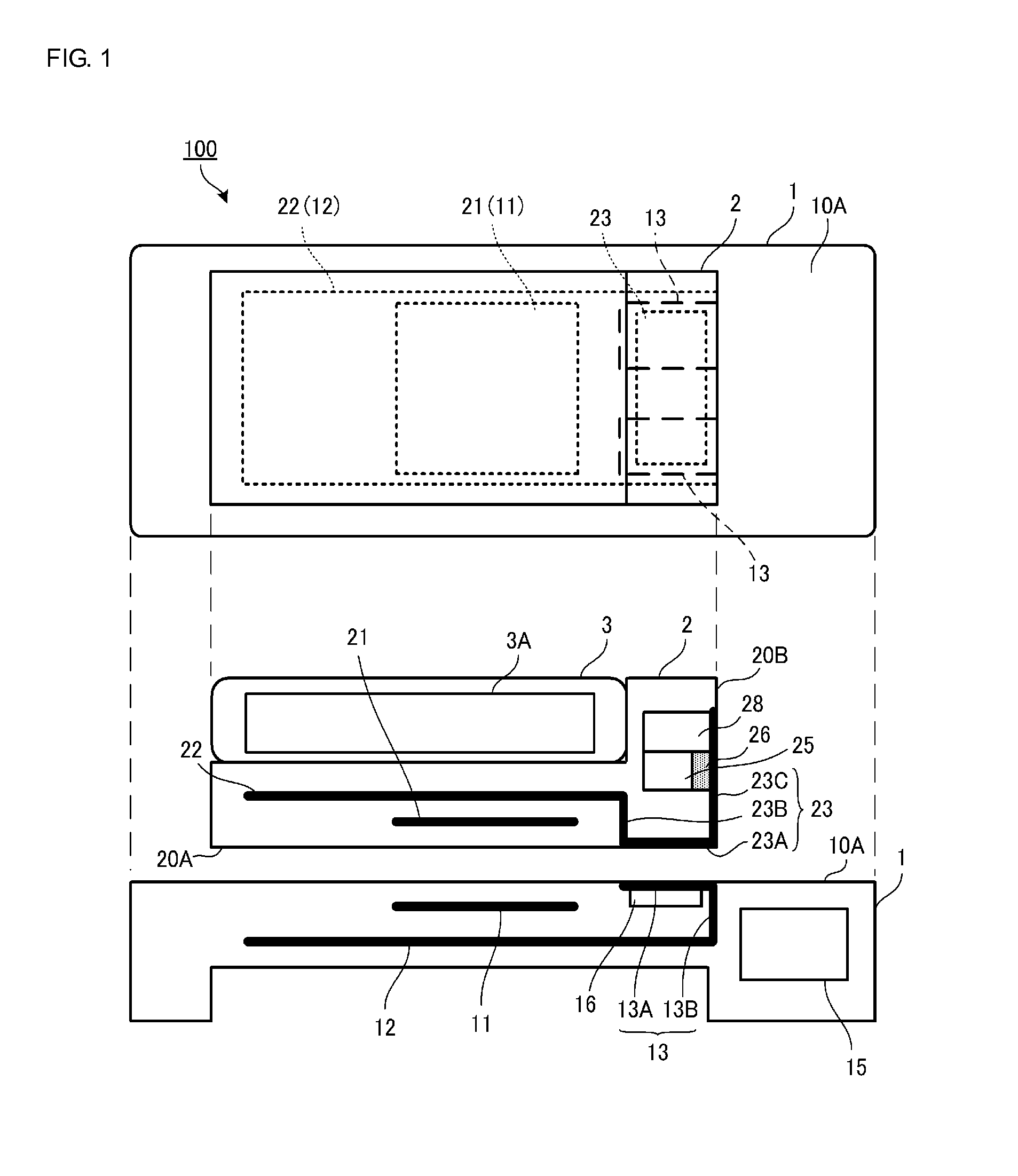
[0023]FIG. 1 shows a plan view and a front cross-sectional view illustrating a wireless power transmission system according to a first embodiment.
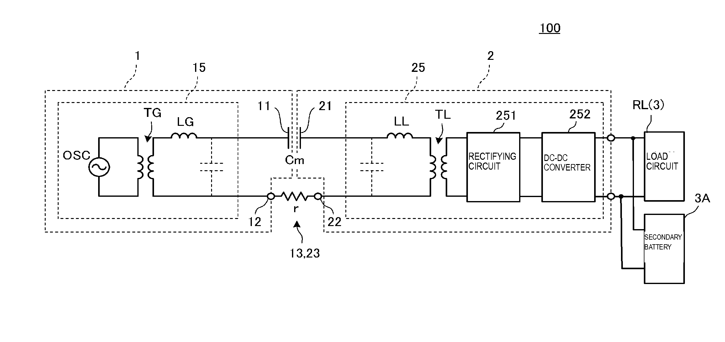
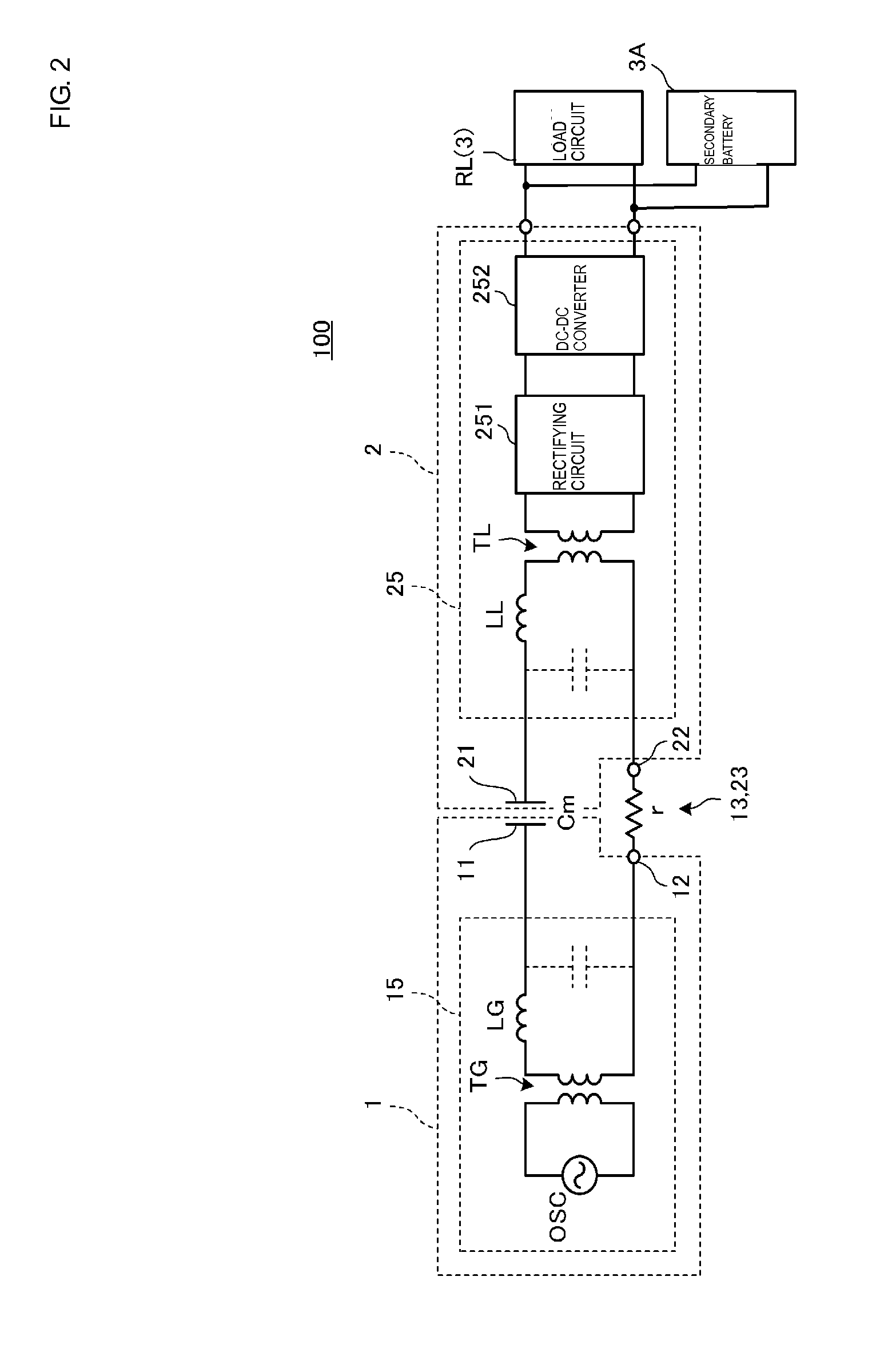
[0024]A wireless power transmission system 100 according to the embodiment is constituted by a power transmitting device 1 and a power receiving device 2. In this example, description is made while the power receiving device 2 is a jacket covering an outer circumferential frame of a tablet-type electronic device 3. In the plan view of FIG. 1, the electronic device 3 is omitted.
[0025]The power receiving device 2 is placed on the power transmitting device 1. As will be described in detail later, a power receiving module 25 is configured in the power receiving device 2. Further, the power receiving module 25 is connected to the electronic device 3 through a connector in the power receiving device 2 and charges a secondary battery 3A of the electronic device 3. That is to say, the power transmitting device 1 is a charging platform of the elect...
second embodiment
[0051]FIG. 3 is a front cross-sectional view illustrating a wireless power transmission system according to a second embodiment. The second embodiment is different from the first embodiment in a point that the heat conducting plate 13 of a power transmitting device 1A and the heat conducting plate 23 of a power receiving device 2A do not make contact with each other directly. It should be noted that the same reference numerals as those in the first embodiment denote the same members and description thereof is omitted.
[0052]The heat conducting plate 23 included in the power receiving device 2A is not exposed to the rear surface 20A of the power receiving device 2A and is provided at the inner side from the rear surface 20A. A heat transfer member 27 having electric insulating property is provided between the heat conducting plate 23 and the rear surface 20A. In other words, the heat conducting plate 23 is covered with the heat transfer member 27 so as not to be exposed from the housi...
PUM
 Abstract
Description
Claims
Application Information
 - Generate Ideas
- Intellectual Property
- Life Sciences
- Materials
- Tech Scout
- Unparalleled Data Quality
- Higher Quality Content
- 60% Fewer Hallucinations
Browse by: Latest US Patents, China's latest patents, Technical Efficacy Thesaurus, Application Domain, Technology Topic, Popular Technical Reports.
© 2025 PatSnap. All rights reserved.Legal|Privacy policy|Modern Slavery Act Transparency Statement|Sitemap|About US| Contact US: help@patsnap.com