Imaging apparatus

Inactive Publication Date: 2015-07-30
HOYA CORP
View PDF3 Cites 26 Cited by
  • Summary
  • Abstract
  • Description
  • Claims
  • Application Information

AI Technical Summary

Benefits of technology

[0013]Accordingly, the present invention provides an imaging apparatus equipped with an image-stabilizing system which is small in size (especially slim in the forwa

Problems solved by technology

However, movements of an optical element to reduce image shake (image-stabilizing optical element) exert an adverse influence on the optical performance such as aberrations, and a space corresponding to the moving amount of the optical element is required.
In the first type of image-stabilizing system, a substrate which is connected to the image sensor moves while following the image sensor; accordingly, the peripheral electrical components, in addition to the image sensor, need to be designed so as to be compatible with such movements, so that the image-stabilizing system tends to be complicated in structure and high in production cost.
In addition, although the periphery of the imaging surface of the image sensor needs to have a dust-resistant structure, it is difficult to secure a sufficient space which allows the image sensor to perform an image-stabilizing operation while maintaining a dust-resistant structure within a small imaging unit intended to be incorporated in a cellular phone or a smart device.
In the second type of image-stabilizing system, the moving direction of the image-stabilizing lens during an image-stabilizing operation corresponds to the thickness direction of the imaging unit (the forward/rearward direction with the direction toward an object to be photographed set to correspond to the forward direction), s

Method used


Image

  • Imaging apparatus
  • Imaging apparatus
  • Imaging apparatus

Examples


first embodiment

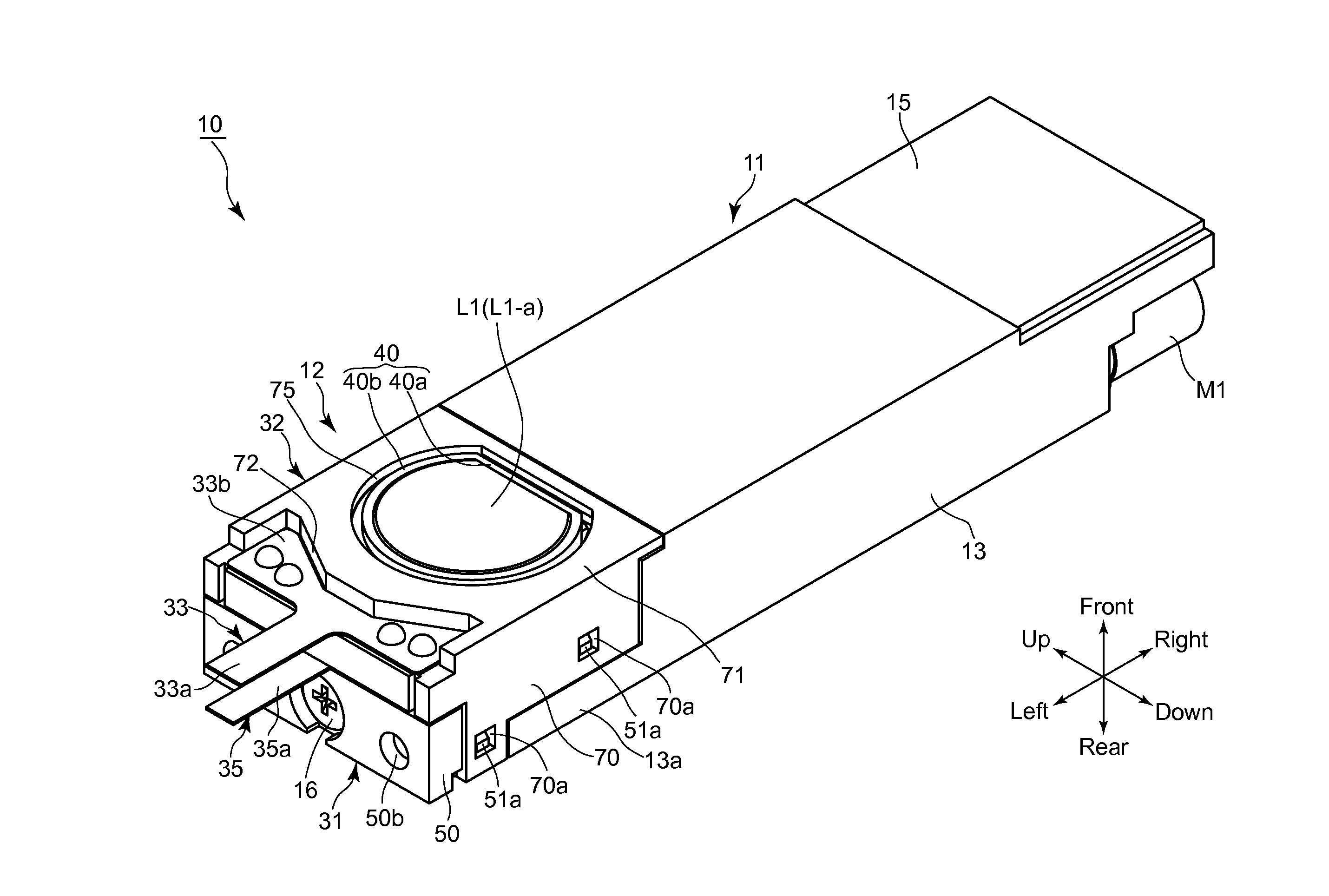
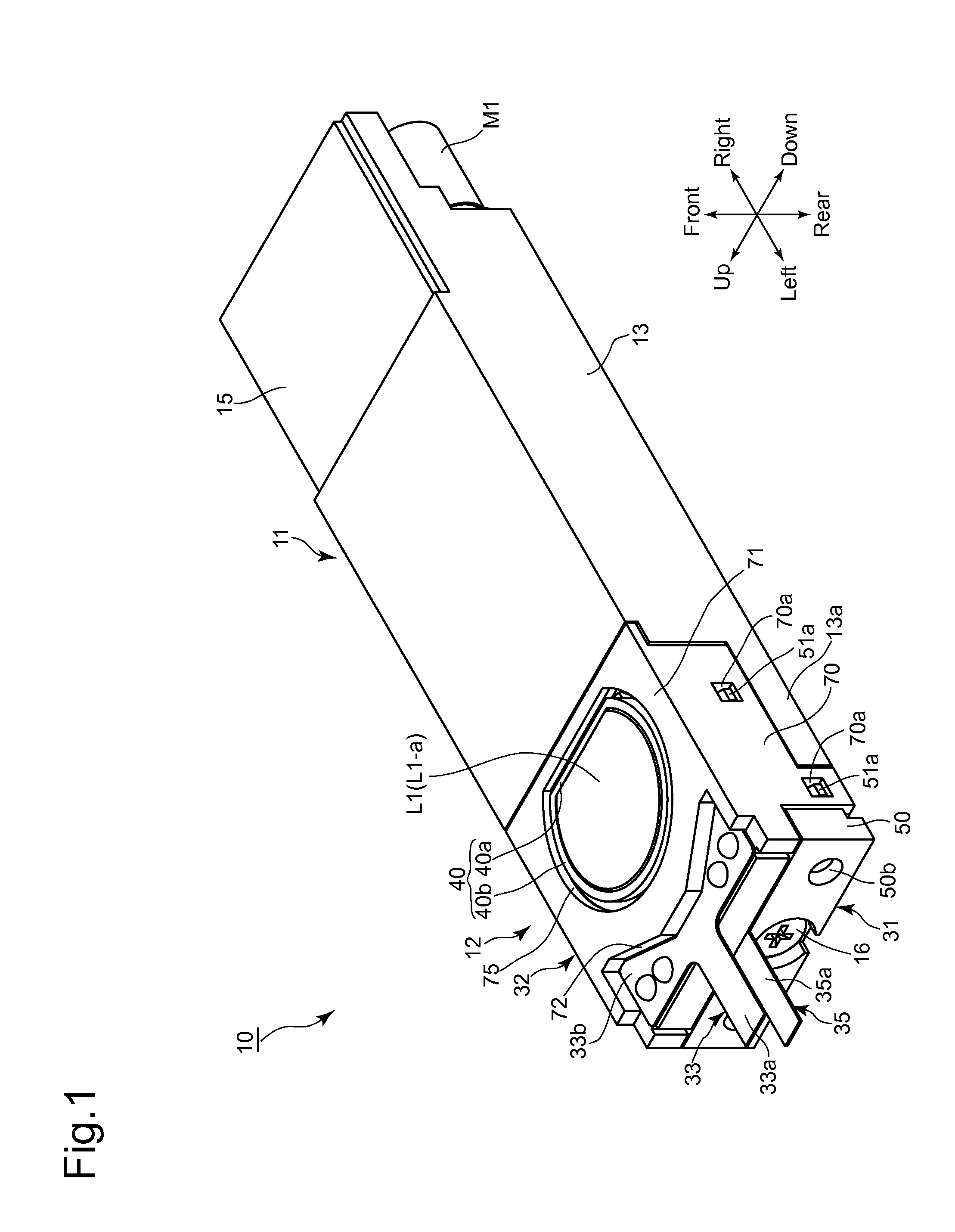
[0082]An embodiment (first embodiment) of an imaging unit (imaging apparatus) 10 according to the present invention will be discussed below with reference to FIGS. 1 through 21. In the following descriptions, forward and rearward directions, leftward and rightward directions, and upward and downward directions are determined with reference to the directions of the double-headed arrows shown in the drawings. The object side corresponds to the front side. As shown by the outward appearance of the imaging unit 10 in FIG. 1, the imaging unit 10 has a laterally elongated shape which is slim in the forward / rearward direction and elongated in the leftward / rightward direction.

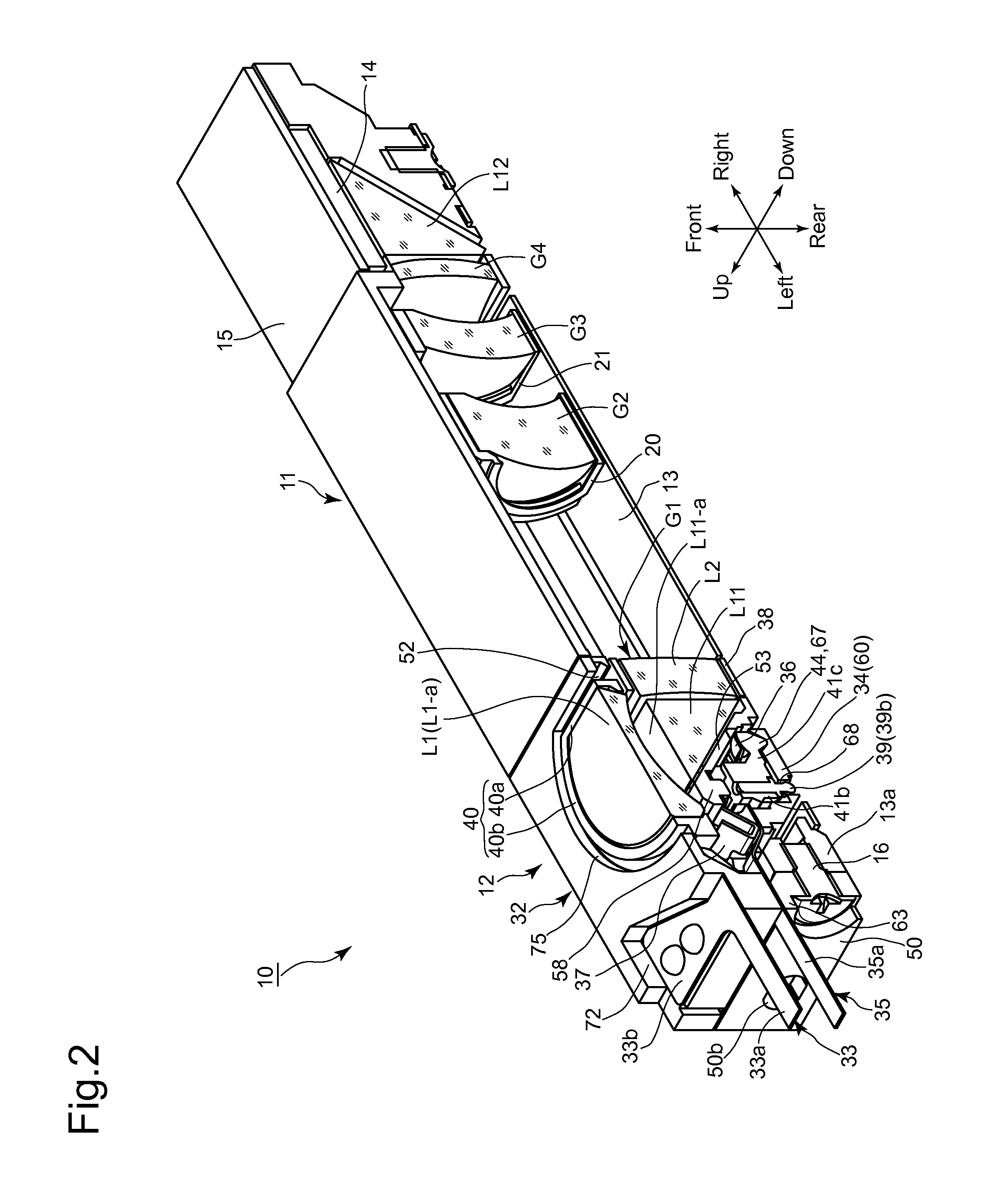
[0083]As shown in FIGS. 2, 4, 6 and 7, an imaging optical system of the imaging unit 10 is provided with a first lens group (front lens group) G1, a second lens group (rear lens group) G2, a third lens group (rear lens group) G3 and a fourth lens group (rear lens group) G4. The first lens group G1 is provided with a fi...

third embodiment

[0147]In the third embodiment shown in FIGS. 25 through 27, a pivot recess (contacting portion / spherical-swinging support portion) 267 which is different in shape from either of the pivot recesses 67 and 167 is formed in the base plate portion 60 of the sensor holder 34. The pivot recess 267 is provided therein with a circular opening 267a and is provided in the base of the opening 267a (in the rearward direction of the imaging unit 10) with a triangular (three-sided) pyramid-shaped recess 267b which has three movement limit sides (inner side walls) 267c. When the triangular pyramid-shaped recess 267b is viewed from front along the first optical axis O1 as shown in FIG. 26, the center of the inscribed sphere which touches each of the three movement limit sides 267c is positioned on an extension of the first optical axis O1.

[0148]In the third embodiment shown in FIGS. 25 through 27, a pivot projection (projecting portion) 244 which is formed on the first lens frame 30 has the same sh...

fifth embodiment

[0150]In the support mechanism shown in FIG. 29, a pivot recess (supported portion) 41d and a pivot recess (spherical-swinging support portion) 60a, the inner surfaces of which face each other, are formed on the pivot arm 41c of the first lens frame 30 and the base plate portion 60 of the sensor holder 34, respectively, and a spherical support ball (spherical-swinging support portion) 45 is sandwiched between the pivot recesses 41d and 60a and is rotatable therebetween. The center of the support ball 45 is coincident with the spherical-swinging center A1, and the first lens frame 30 can be made to perform the spherical swinging operation about the spherical-swinging center A1 by making the inner surfaces of the pivot recesses 41d and 60a come into sliding contact with the periphery of the support ball 45.


PUM


Abstract

An imaging apparatus includes a front lens group having a front lens element and a reflector, in that order from an object side. The reflector includes a reflection surface which reflects light rays, from the front lens element, toward a different direction; a rear lens group positioned closer to an image plane than the front lens group, the imaging apparatus performs an image-stabilizing operation by driving the front lens element, a movable frame holding the front lens element; a support member supporting the reflector and is immovable relative to an optical axis of the front lens element, in a reference state; and a support mechanism which supports the movable frame to spherically swing about a spherical-swinging center, positioned on an extension of the optical axis of the front lens element extending behind an underside of the reflection surface of the reflector.

Description

BACKGROUND OF THE INVENTION[0001]1. Field of the Invention[0002]The present invention relates to an imaging apparatus equipped with an image-stabilizing (image shake correction / shake reduction) system.[0003]2. Description of the Related Art[0004]In recent years, mobile electronic devices which are designed mainly for taking still / moving photographic images, such as digital cameras (still-video cameras) and digital camcorders (motion-video cameras), and other mobile electronic devices which are designed to be capable of taking such photographic images as a subsidiary function, such as mobile phones equipped with a camera and smart devices (smart phones or tablet computers, etc.) equipped with a camera, have become widespread, and there has been a demand to miniaturize the imaging units incorporated in these types of mobile electronic devices. In order to miniaturize an imaging unit, it is known in the art to construct an optical system of an imaging unit as a bending optical system w...

Claims


Application Information

Patent Timeline
IPC IPC(8): H04N5/232H04N5/225
CPCH04N5/23287H04N5/23283H04N5/2254H04N23/55H04N23/687G03B5/00G02B27/646G02B7/023G02B13/005G02B13/0065H04N23/686
Inventor NOMURA, HIROSHISUZUKA, SHINYAMORINAGA, TAKAHIRONAKAMURA, TOSHIKITADA, EIJIROH
Owner HOYA CORP
Why Eureka
Try Eureka