Poultry euthanasia device

a technology for euthanasia and poultry, which is applied in the field of poultry processing, can solve the problems of shards ending up, cost prohibitive, and animal welfare concerns have become a much larger issue, and achieve the effects of reducing the number of birds, facilitating the euthanasia process, and ensuring the welfare of chickens

Active Publication Date: 2015-08-06
MOYLE RYAN
View PDF8 Cites 5 Cited by
  • Summary
  • Abstract
  • Description
  • Claims
  • Application Information

AI Technical Summary

Benefits of technology

[0026]With minimal modification to the wall of the barn, one can penetrate the side of the wall with the entry chute in such a way that no light comes in around the chute. This allows for the workers to keep all the doors closed and work in low light conditions that keep the chickens much more calm and at ease. It is easier on the birds and makes catching them much easier.
[0027]The device of the disclosed technology allows for ground floor or second flood loading of birds. A short entry chute is to be used in the case of ground floor loading and a longer entry chute for second floor loading. Moreover, a chute adaptor is included that allows the angle of the chute to be at an adjustable angle.

Problems solved by technology

1. Consolidation of poultry meat processing plants has led to their sparse disbursement across America. Therefore, many egg farms are simply too far away to transport the birds, making it cost prohibitive.
2. Transportation of these old hens is complicated by the hens tendency to have brittle bones. This has led to problems with animal welfare issues, and problems with bone shards ending up in the chicken soup. Therefore, on-farm euthanasia for delivery to a rendering plant or composting has become much more a necessity.
Animal welfare concerns have become a much larger issue over the years.
Additionally, states are passing animal cruelty laws that are vague at best.
They may have the USDA or CDC forcing them to depopulate their flock on-farm, but lack the tools to do so and satisfy AVMA guidelines.
One such method is Modified Atmospheric Killing (MAK) carts, but it is slow, inconsistent, and archaic and labor intensive.
There is no way to accurately measure the CO2 concentration, and it is all guesswork.
Either way, the doors to the barn are open and the increased light makes the animals more nervous and difficult to catch.
Moreover, many carts are needed.
This is very hard on the birds as they are tossed about and these old hens have brittle bones which break easily.
Lots of CO2 is wasted because the whole volume of the truck is gassed, then the door is opened for the next batch allowing the CO2 to escape, so it is not efficient.

Method used


Image

  • Poultry euthanasia device
  • Poultry euthanasia device
  • Poultry euthanasia device

Examples


Embodiment Construction

[0038]While the presently disclosed inventive concept(s) is susceptible of various modifications and alternative constructions, certain illustrated embodiments thereof have been shown in the drawings and will be described below in detail. It should be understood, however, that there is no intention to limit the inventive concept(s) to the specific form disclosed, but, on the contrary, the presently disclosed and claimed inventive concept(s) is to cover all modifications, alternative constructions, and equivalents falling within the spirit and scope of the inventive concept(s) as defined in the claims.

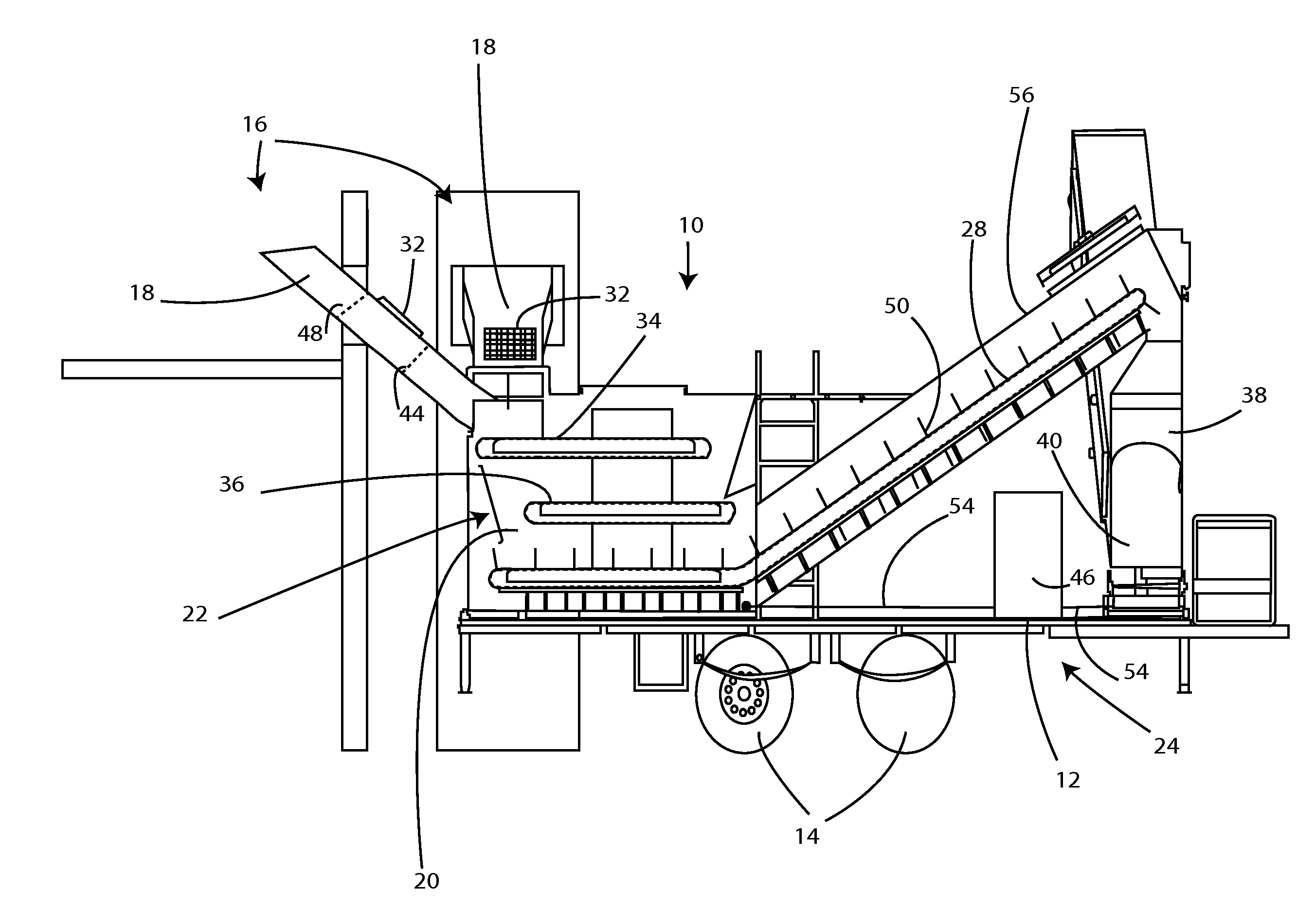
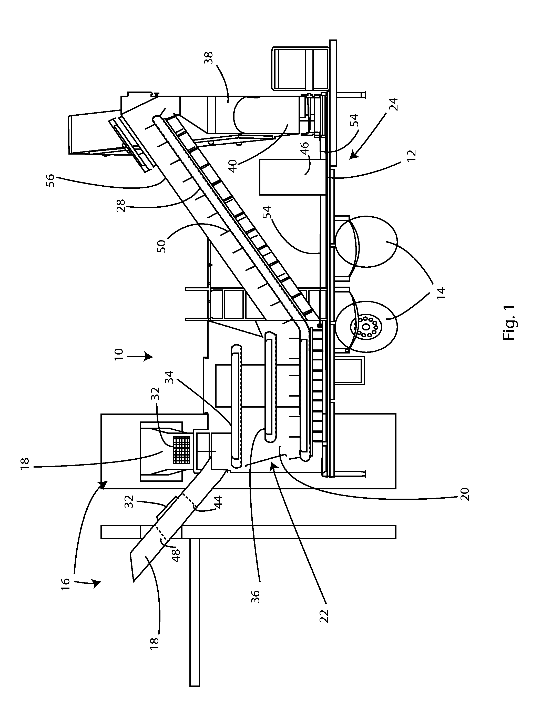
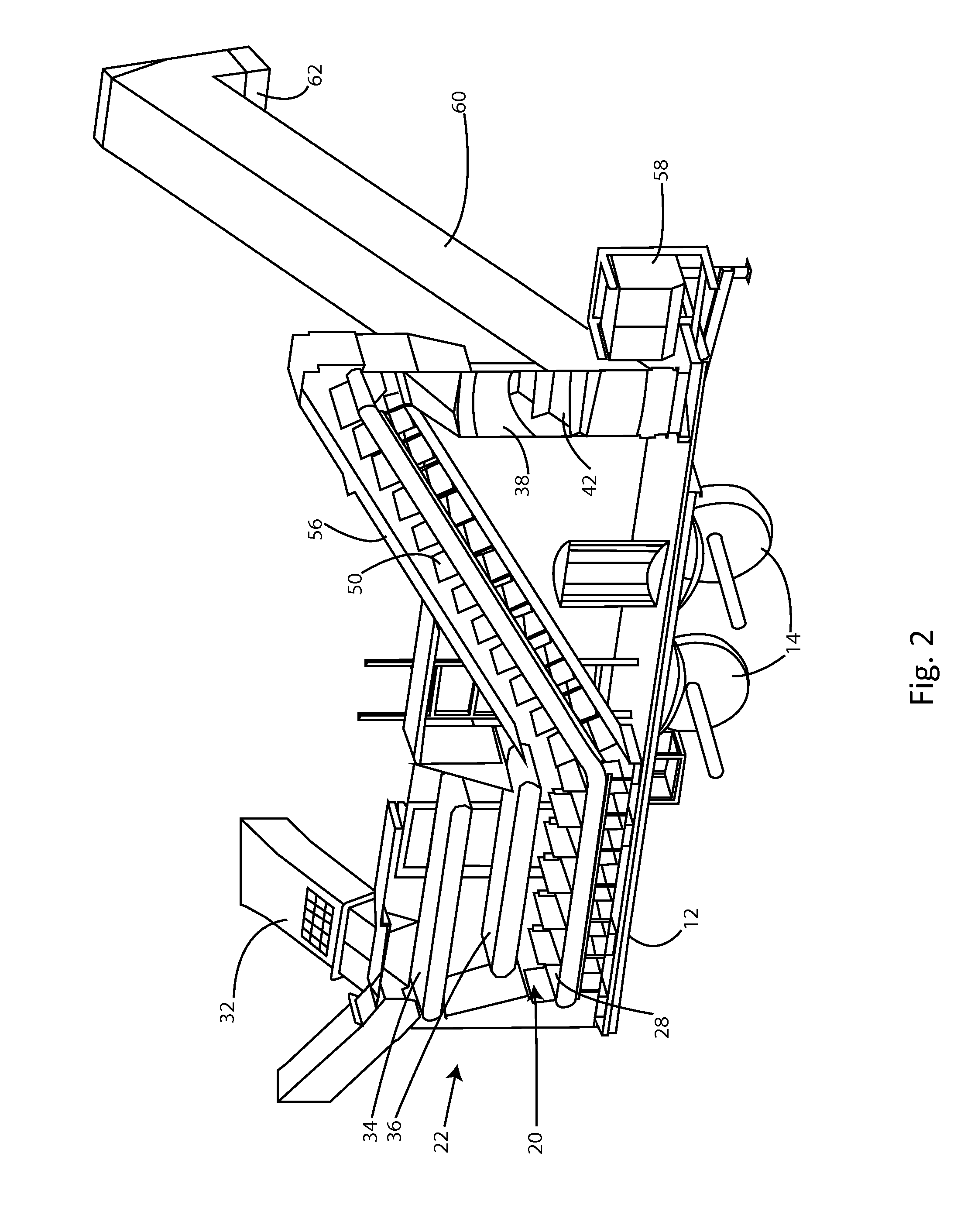
[0039]Preferred embodiments of the disclosed technology are shown in the FIGS. 1-_. FIG. 1 shows the euthanasia device 10, referred to as the hen sleeper 10. The hen sleeper 10 is mounted on the trailer 12 which is transported by use of wheels 14. The hen sleeper 10 is positioned adjacent to a hen house 16 as an example. An entry chute 18 is inserted through the wall of the hen house 16...


PUM


Abstract

A poultry euthanasia device in which hens pass on belts though a gas proof enclosure with increasing concentration levels of toxic gas for more humane euthanasia, and exit the machine deceased. The device has an entry chute which is connectable to a hen house located to either side of the unit, or behind the unit. A number of belts carry the hens through the machine, and they painlessly go to sleep and die due to a high CO2 atmosphere.

Description

PRIORITY / CROSS-REFERENCE TO RELATED APPLICATIONS[0001]This application claims the benefit of U.S. Provisional Application No. 61 / 935,228, filed Feb. 3, 2014 the disclosure of which is incorporated by reference.TECHNICAL FIELD[0002]The presently disclosed technology relates to poultry processing, and more specifically to poultry euthanasia.BACKGROUND[0003]Presently there is a great need for an efficient method to euthanize spent laying hens with an emphasis on concern for the animal's welfare. Historically, spent laying hens had been processed for human consumption, however, there has been a great decline in this practice for the following reasons:[0004]1. Consolidation of poultry meat processing plants has led to their sparse disbursement across America. Therefore, many egg farms are simply too far away to transport the birds, making it cost prohibitive.[0005]2. Transportation of these old hens is complicated by the hens tendency to have brittle bones. This has led to problems with ...

Claims


Application Information

Patent Timeline
Patent Type & Authority Applications(United States)
IPC IPC(8): A22B3/00A22C21/00A22B3/08
CPCA22B3/005A22C21/0053A22B3/08A01K45/005A22B3/086
Inventor MOYLE, RYAN
Owner MOYLE RYAN
Why Eureka
Try Eureka