Brake control system for a utility vehicle having a trailer

a technology for brake control and utility vehicles, applied in the field of vehicles, can solve the problems of vehicle rolling backwards, vehicle hitting its limits, etc., and achieve the effect of low overall for

Inactive Publication Date: 2015-08-06
KNORR-BREMSE SYST FUER NUTZFAHRZEUGE GMBH
View PDF9 Cites 5 Cited by
  • Summary
  • Abstract
  • Description
  • Claims
  • Application Information

AI Technical Summary

Benefits of technology

[0012]Therefore, a flow of compressed air from the common port of the two non-return valves to the respective remaining separate ports of the two non-return valves is avoided, but permitted in the opposing direction. The shuttle valve therefore ensures a compressed air flow exclusively from the vehicle pressure path or the start assist circuit into the trailer pressure path, but not in any other direction.
[0013]In one particular development, the specified brake control device comprises a pressure valve which is provided for adjusting a level of the further brake pressure. This pressure valve can be embodied, for example, as an actuator element of a control circuit which adjusts the level of the brake pressure on the basis of whether the utility vehicle is moving, with the re...

Problems solved by technology

For technical reasons, within the scope of the hill start assist system only the drive axle should be braked, as a result of which, however, the hill start assist system comes up against its limits relatively quickly relatively large g...

Method used


Image

  • Brake control system for a utility vehicle having a trailer
  • Brake control system for a utility vehicle having a trailer
  • Brake control system for a utility vehicle having a trailer

Examples


Embodiment Construction

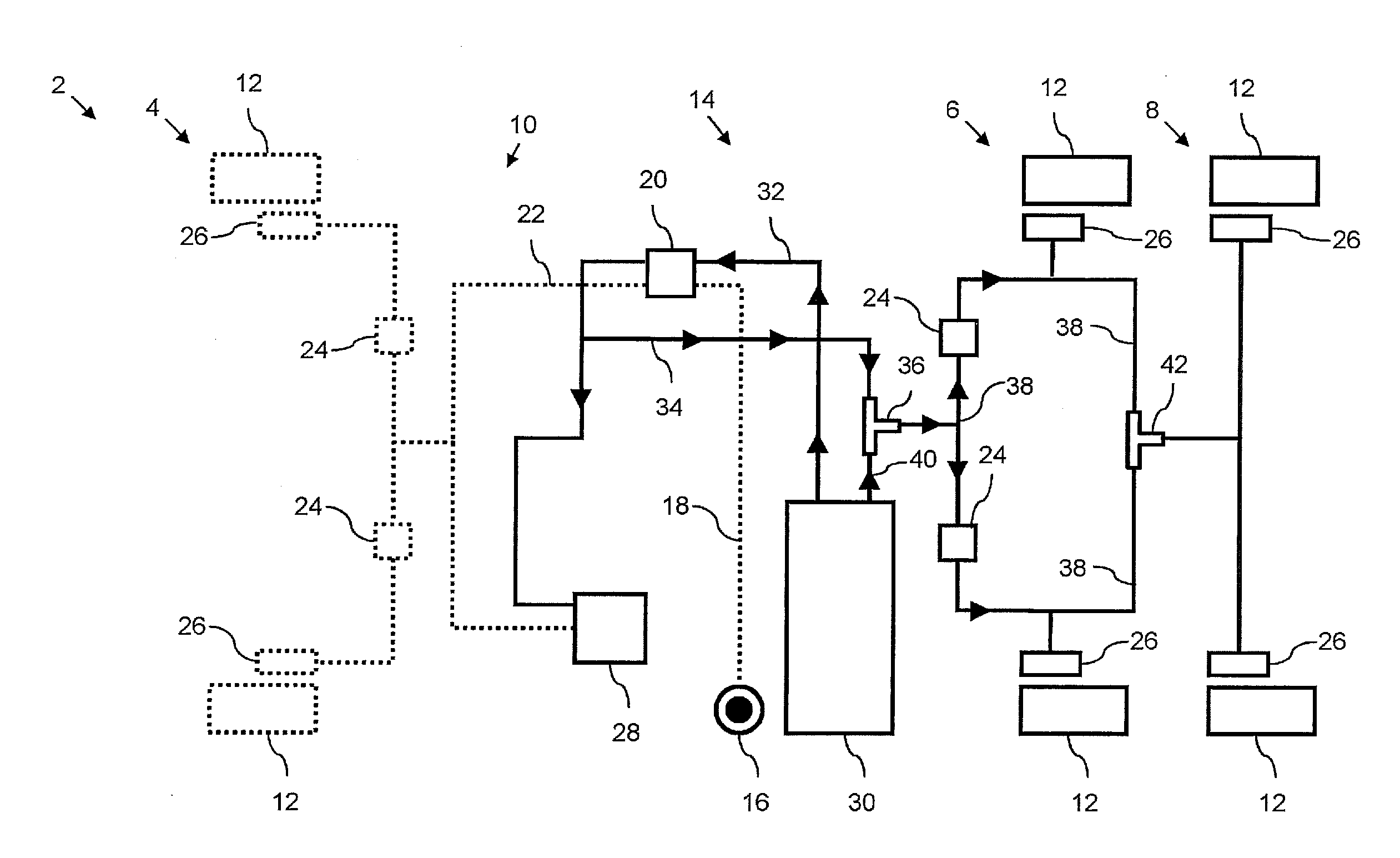
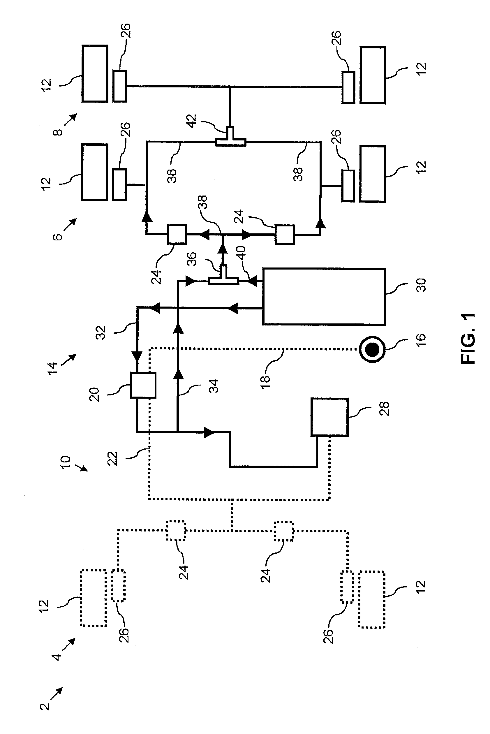
[0026]In the figures, identical technical elements are provided with identical reference symbols and described only once.

[0027]Reference is made to FIG. 1 which shows a dual-circuit brake system 2 of a utility vehicle (not illustrated in detail) with a front axle 4 and two rear axles 6, 8. Here, the first rear axle 6 is located upstream of the second rear axle 8 viewed from the front axle 4. The utility vehicle can also be constructed with two axles, details of which are given here at the correspondingly relevant points in the following description.

[0028]In the present embodiment, the dual-circuit brake system 2 comprises a first brake circuit 10 for braking the wheels 12 on the front axle 4, which is indicated in FIG. 1 by dotted lines. A second brake circuit 14 of the dual-circuit brake system 2, which is indicated by continuous lines in the figures, is provided for braking the wheels 12 on the two rear axles 6, 8. In the present embodiment, for the sake of simplicity control brak...


PUM


Abstract

A brake control device for a utility vehicle having a trailer, including: a pneumatic brake control circuit having a vehicle pressure path to output a brake pressure to a vehicle brake which brakes the utility vehicle, based on a target input of a driver of the utility vehicle, and having a trailer pressure path for outputting the brake pressure to a trailer brake, which brakes the trailer, on the basis of the target input; and a pneumatic start assist circuit to output a further brake pressure to a trailer brake of the trailer based on a speed of the utility vehicle, in which the pneumatic start assist circuit is pneumatically connected to the trailer pressure path of the pneumatic brake control circuit.

Description

FIELD OF THE INVENTION[0001]The present invention relates generally to vehicles and, in particular, utility vehicles. Furthermore, the invention relates to a brake control device for a utility vehicle having a trailer.BACKGROUND INFORMATION[0002]German patent document DE 10 2010 039 301 A1 discusses a hill start assist system, also referred to as HSA for hill start aid. Such a hill start assist system assists a driver of a utility vehicle when starting on gradients, which driver must simultaneously keep the vehicle stationary with the foot brake, open the throttle and activate the clutch at the same time.SUMMARY OF THE INVENTION[0003]It is an object of the invention to provide an improved hill start assist system.[0004]The object may be achieved by the features of the independent claims. Developments are the subject matter of the further descriptions herein.[0005]According to one aspect of the invention, a brake control device for a utility vehicle having a trailer comprises:[0006]a...

Claims


Application Information

Patent Timeline
IPC IPC(8): B60T8/17B60T8/48B60T8/24
CPCB60T7/122B60T7/20B60T13/683B60T8/4818B60T8/1708B60T8/245B60T2201/06
Inventor HECKER, FALKWIEDER, GERHARDMUSTAPHA, ADNAN
Owner KNORR-BREMSE SYST FUER NUTZFAHRZEUGE GMBH
Why Eureka
Try Eureka