
Relay Control System and Method for Controlling Same

Active Publication Date: 2015-08-06
SK ON CO LTD
View PDF4 Cites 13 Cited by
  • Summary
  • Abstract
  • Description
  • Claims
  • Application Information

AI Technical Summary

Benefits of technology

The present invention is about a relay control system that can identify which main relay is malfunctioning before turning it on. This makes it possible to improve the stability of the battery management system and charge both positive and negative terminals of the battery pack.

Problems solved by technology

However, since controllers (HCU, MCU, GCU, and the like) do not share a request signal for turning off the main relay with each other, each of the controllers may not know whether the battery management system is requested for turning off the main relay by other controllers.
Due to the fused main relay, since the battery management system does not manage the SOC or the like of the main battery, overcharge or over-discharge of the main battery may be caused and the overcharge or over-discharge of the main battery may cause explosion of the battery and a danger of an electric shock to a driver.

Method used


Image

  • Relay Control System and Method for Controlling Same
  • Relay Control System and Method for Controlling Same
  • Relay Control System and Method for Controlling Same

Examples


Embodiment Construction

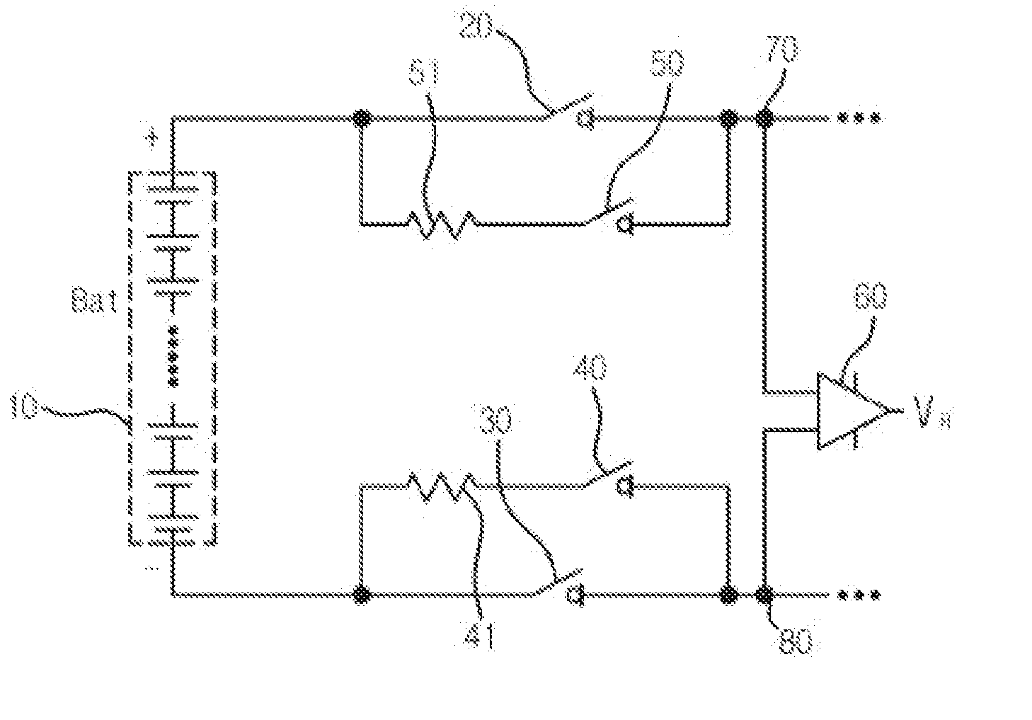
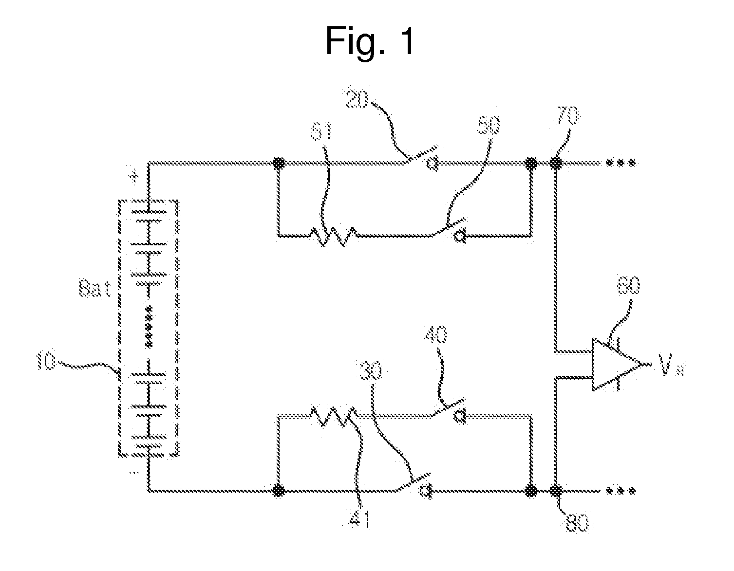
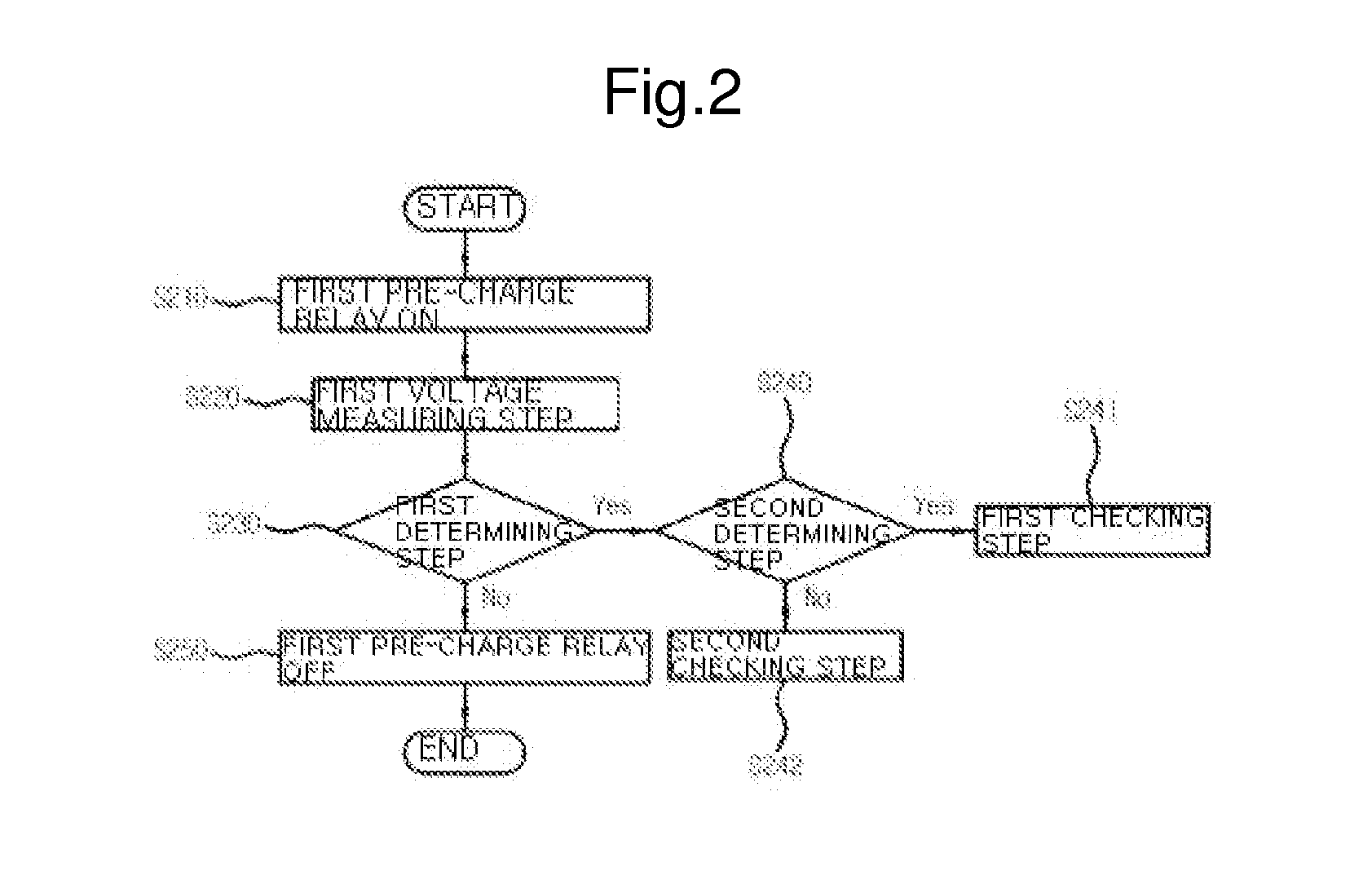
[0026]Hereinafter, a relay control system of the present invention will now be described in detail with reference to the accompanying drawings. The drawings set forth below are provided as examples so that technical ideas of the present invention are sufficiently delivered to those skilled in the art. Therefore, the present invention may not be limited to the drawings set forth below and may be embodied in different forms. In addition, like reference numerals refer to like elements throughout the overall specification.

[0027]Unless otherwise defined in technical and scientific terms, all terms used herein have the same meaning as commonly understood by one of ordinary skill in the art to which this invention pertains, and detailed descriptions of well-known functions or configurations in the drawings will be omitted in order not to unnecessarily obscure the focus of the present invention.

[0028]FIG. 1 is a view schematically illustrating a configuration of a relay control system accor...


PUM


Abstract

The present invention relates to a relay control system and a control method thereof, and more particularly, to a relay control system and a control method thereof capable of determining whether an unrecoverable failure of a relay due to an unexpected environment, namely, whether the relay is fused, by measuring a voltage on a relay in real time while a battery unit operates in a secondary cell battery using DC power.

Description

TECHNICAL FIELD[0001]The present invention relates to a relay control system and a control method thereof, and more particularly, to a relay control system and a control method thereof capable of determining whether an unrecoverable failure of a relay due to an unexpected environment, namely, whether the relay is fused, by measuring a voltage on a relay in real time while a battery unit operates in a secondary cell battery using DC power.BACKGROUND ART[0002]Unlike an existing internal combustion engine, an electric vehicle (e.g., HEV, PHEV, BEV, or the like) uses electricity as main power or auxiliary power and, to this end, a high voltage battery is mounted thereon to be used. At this point, a battery management system is a controller entirely managing the main battery, which includes measuring a state of charge (SOC) of the high voltage battery. The battery management system allows voltages necessary for driving and controlling the vehicle to be provided from the main battery to e...

Claims


Application Information

Patent Timeline
IPC IPC(8): G01R31/327
CPCH01M10/42H01M10/46G01R31/3278H01M2220/20H01M2010/4271Y02E60/10H02H7/18H02J7/00
Inventor HUH, GEUN HOE
Owner SK ON CO LTD
Learn More