Electronic Timepiece

a technology of electronic timepieces and timepieces, applied in the field of electronic timepieces, can solve the problems of low shape flexibility, the antenna body having a complicated shape cannot be made of ceramic materials or any other dielectric, and the antenna body's reception sensitivity decreases, so as to enhance the wavelength shortening

Active Publication Date: 2015-08-06
SEIKO EPSON CORP
View PDF12 Cites 21 Cited by
  • Summary
  • Abstract
  • Description
  • Claims
  • Application Information

AI Technical Summary

Benefits of technology

[0008]An advantage of some aspects of the invention is to provide an electronic timepiece capable of enhancing a wavelength shortening effect achieved by an antenna body made of a dielectric.
[0010]In the aspect of the invention, since the dielectric auxiliary member having a dielectric constant greater than the dielectric constant of the base of the antenna body is disposed along the antenna body, a wavelength shortening effect achieved by the antenna body containing a dielectric can be enhanced, whereby the size of the antenna body can be reduced. An antenna body basically needs to have a length equal to one-half the wavelength of electrical radiation to be transmitted and received. Even when a dielectric is used to achieve wavelength shortening, transmission and reception of 1.5-GHz electrical radiation used in a GPS and 2.4-GHz electrical radiation used in Bluetooth (registered trademark) requires an antenna length of several centimeters. In the invention, since the antenna body is disposed around the time display section, the space in the timepiece is efficiently used. In the invention, “containing a dielectric” includes a case where a component is made of a resin or any other material mixed with a dielectric material, and a case where a component is made only of a dielectric material, such as a ceramic material. The same holds true for the rest of the present specification.
[0012]In the electronic timepiece according to the aspect of the invention described above, the case may have a portion that is made of a metal and covers at least part of the antenna body in a side view of the electronic timepiece or the case may have a member that is made of a metal and located on a portion of the case that covers the part of the antenna body in a side view of the electronic timepiece, and the dielectric auxiliary member may be disposed between the antenna body and the portion made of a metal or the member made of a metal. When a metal is present in a portion that covers the antenna body in a side view of the electronic timepiece, it is conceivable that the metal undesirably blocks electrical radiation carrying a signal to be received, resulting in a decrease in reception sensitivity of the antenna body. According to the aspect of the invention, since the dielectric auxiliary member is disposed between the portion made of a metal or the member made of a metal and the antenna body, a large wavelength shortening effect is achieved, whereby the size of the antenna body can be reduced, and the portion made of a metal or the member made of a metal can be appropriately set apart from the antenna body. The reception sensitivity of the antenna body therefore does not lower. Further, the portion of the case that covers the antenna body can be made of a metal, or a member made of a metal can be provided in the portion of the case that covers the antenna body, whereby design flexibility can be increased.
[0013]In the electronic timepiece according to the aspect of the invention described above, the member made of a metal and located in a portion of the case that covers at least the antenna body may be attached to a member made of a resin. In this case, since the dielectric auxiliary member is disposed between the member made of a metal and the antenna body, a large wavelength shortening effect is achieved, whereby the size of the antenna body can be reduced, and the member made of a metal can be appropriately set apart from the antenna body. The reception sensitivity of the antenna body therefore does not lower. Further, a member made of a metal can be provided on the portion of the case that covers the antenna body, whereby design flexibility can be increased.
[0015]In the electronic timepiece according to the aspect of the invention described above, the base of the antenna body may have a recess formed therein and the recess may prevent the base from interfering with another member, or the base of the antenna body may have a fixing portion formed therein and the fixing portion may fix the antenna body to the base. In this case, forming the recess or the fixing portion in the antenna body allows a narrow space to be effectively used to accommodate a large number of parts and components in the case. To form the recess or the fixing portion in the antenna body, the hardness of the antenna body needs to be low, and it is therefore difficult to form the antenna body, for example, by using a ceramic material, which has a large dielectric constant. In the aspect of the invention, the dielectric auxiliary member having hardness higher than that of the antenna body is provided around the antenna body. Therefore, for example, forming the dielectric auxiliary member by using a ceramic material having a large dielectric constant allows the recess or the fixing portion to be formed in the antenna body and a large wavelength shortening effect to be achieved at the same time.

Problems solved by technology

However, a ceramic material or any other dielectric is difficult to process and therefore has a problem of low shape flexibility.
In an electronic timepiece that accommodates a large number of parts in a narrow space, in particular, it is necessary to form the antenna body in a complicated shape in some cases, but the antenna body having a complicated shape cannot be made of a ceramic material or any other dielectric.
When a metal is present in a portion that covers the antenna body in a side view of the electronic timepiece, it is conceivable that the metal undesirably blocks electrical radiation carrying a signal to be received, resulting in a decrease in reception sensitivity of the antenna body.
To form the recess or the fixing portion in the antenna body, the hardness of the antenna body needs to be low, and it is therefore difficult to form the antenna body, for example, by using a ceramic material, which has a large dielectric constant.

Method used


Image

  • Electronic Timepiece
  • Electronic Timepiece
  • Electronic Timepiece

Examples


first embodiment

A. Mechanical Configuration of Electronic Timepiece with Built-in Antenna

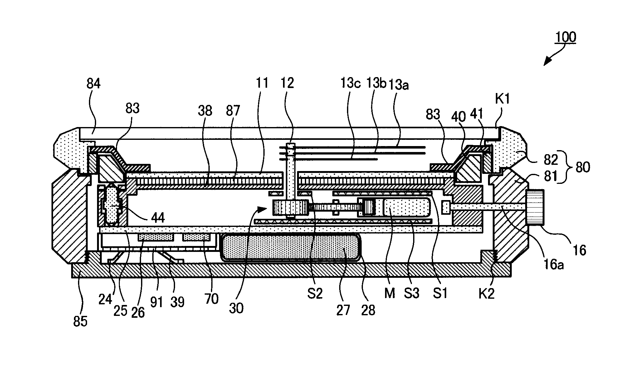
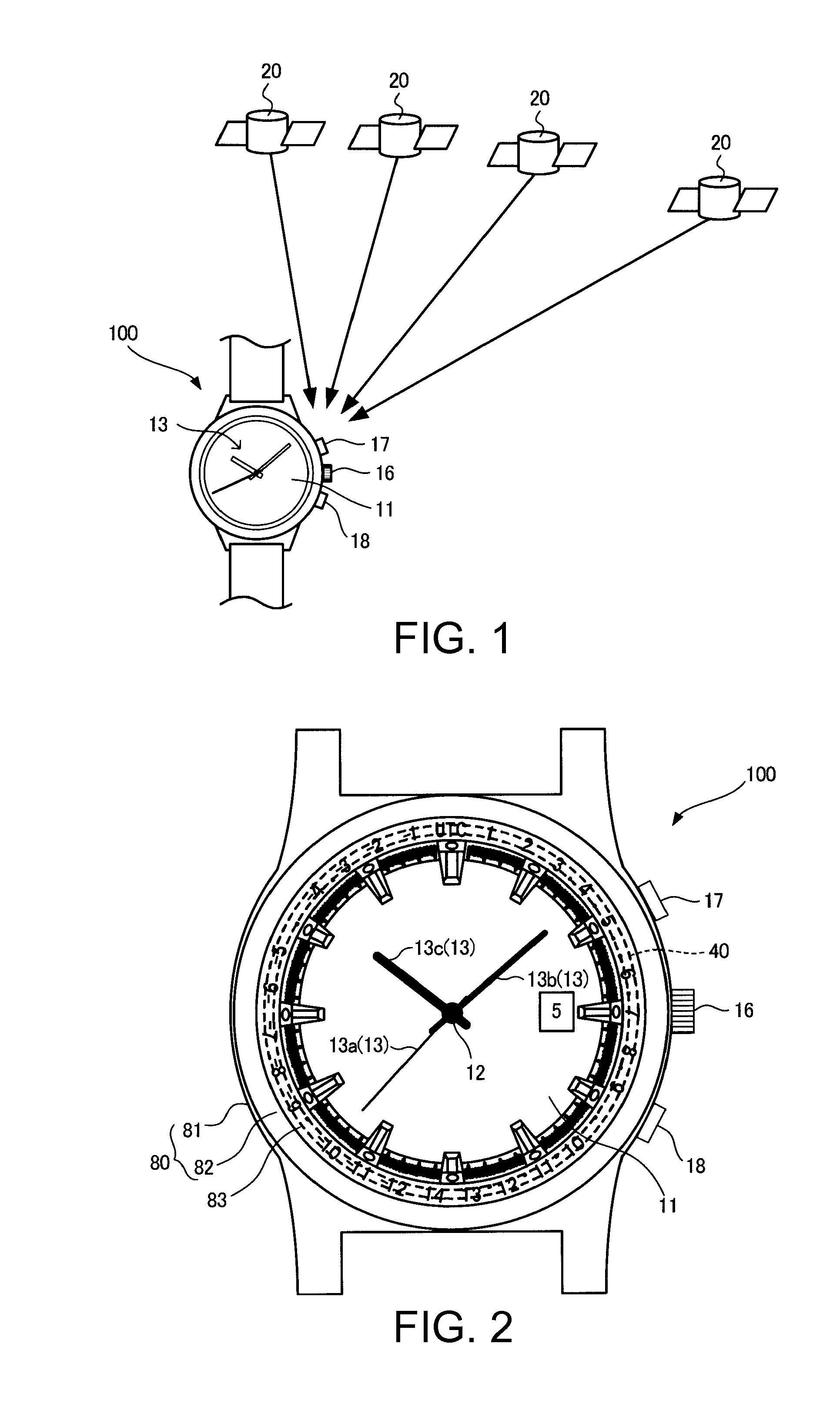
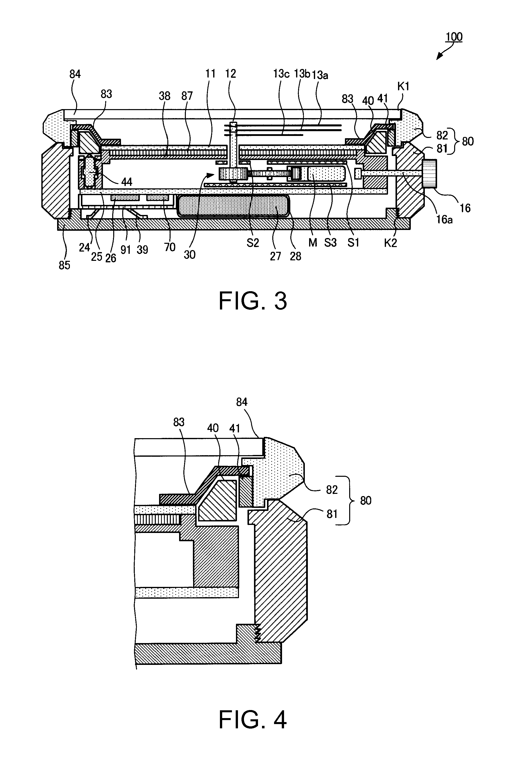
[0032]FIG. 1 is a schematic view showing an overall GPS system including an electronic timepiece 100 with a built-in antenna (hereinafter referred to as “electronic timepiece 100”) according to a first embodiment of the invention. The electronic timepiece 100 is a wristwatch that receives electrical radiation (wireless signal) from at least one of a plurality of GPS satellites 20 to correct internal time, and the electronic timepiece 100 displays time on the side (hereinafter referred to as “front side”) of the timepiece that faces away from the side in contact with an arm (hereinafter referred to as “rear side”). In the following description, the rear side is called a “lower side,” and the front side is called an “upper side.”

[0033]Each of the GPS satellites 20 is a position information satellite that goes along a predetermined orbit around the earth up in the sky and transmits 1.57542-GHz electrical radiation...

second embodiment

[0095]A second embodiment of the invention will next be described with reference to FIG. 9. The first embodiment has been described with reference to the case where the dielectric auxiliary member 41 has a rectangular cross-sectional shape. The present embodiment will be described with reference to a case where the dielectric auxiliary member 41 has an L-like cross-sectional shape. The same components as those in the first embodiment will not be described.

[0096]The dielectric auxiliary member 41 in the present embodiment is made of a ceramic material, such as zirconia (ZrO2), and has an L-like cross-sectional shape, as shown in FIG. 9. Specifically, part of the dielectric auxiliary member 41 is disposed between the antenna body and the case, and the other part is disposed between the antenna body and the cover glass plate. That is, the dielectric auxiliary member 41 also covers the upper surface of the antenna body 40 in FIG. 9. The first antenna pattern 415 is formed on the upper s...

third embodiment

[0100]A third embodiment of the invention will next be described with reference to FIG. 10. FIG. 10 is a cross-sectional view showing the antenna body 40 and components therearound in a digital timepiece 101 according to the present embodiment. The above embodiments have been described with reference to the case where the invention is applied to an electronic timepiece with a dial and indication hands. On the other hand, the present embodiment relates to a case where the invention is applied to a digital timepiece using a liquid crystal panel as the time display section.

[0101]The case 80 shown in FIG. 10 is made of a resin, and a liquid crystal panel 88 is disposed below the cover glass plate 84. In the present embodiment, the first antenna pattern 415 and the second antenna pattern 416 are formed on the upper surface of the antenna body 40 as in the embodiments described above, and an antenna connection pattern (not shown) is directly connected to the circuit substrate 25 via no fe...


PUM


Abstract

An electronic timepiece includes a case formed of a metal case barrel and a metal bezel, and the case accommodates an antenna body made of a resin mixed with a dielectric material and having an annular shape. A dielectric auxiliary member made of a dielectric having a dielectric constant greater than that of the antenna body and having an annular shape is disposed between the antenna body and the bezel.

Description

BACKGROUND[0001]1. Technical Field[0002]The present invention relates to an electronic timepiece with an antenna body.[0003]2. Related Art[0004]As an electronic timepiece that receives electrical radiation, for example, from a GPS satellite, an electronic timepiece with a built-in antenna body has been proposed. In particular, to improve sensitivity at which the antenna body receives electrical radiation, the antenna body is formed in a ring shape (JP-A-2013-64723, for example).[0005]The antenna body described in JP-A-2013-64723 is so configured that an antenna base made of a resin mixed with a dielectric material is formed in a ring shape and an antenna electrode pattern is formed on the antenna base.[0006]An electronic timepiece of the type described above uses a wavelength shortening effect achieved by a dielectric to reduce the size of the antenna body. To further enhance the wavelength shortening effect, it is conceivable to use a ceramic material or any other dielectric having...

Claims


Application Information

Patent Timeline
Patent Type & Authority Applications(United States)
IPC IPC(8): G04G17/04
CPCG04G17/04G04R60/00G04R60/06G04R60/08G04R60/10G04R60/12
Inventor FUJISAWA, TERUHIKO
Owner SEIKO EPSON CORP
Why Eureka
Try Eureka