Electronic device, network relay device, and non-transitory computer readable storage medium

a network relay and electronic device technology, applied in the field of relaying an internet protocol (ip) packet, can solve the problems of recent depletion of newly allocatable ipv4 addresses, and achieve the effects of reducing device size, saving resources, and reducing costs

Active Publication Date: 2015-08-06
BUFFALO CORP LTD
View PDF5 Cites 10 Cited by
  • Summary
  • Abstract
  • Description
  • Claims
  • Application Information

AI Technical Summary

Benefits of technology

[0007]For example, one aspect of the disclosure may be implemented as a device including one or more components out of two components, i.e., a packet relay processor and an operation mode setter. In other words, this device may be configured with or without the packet relay processor. This device may also be configured with or without the operation mode setter. The packet relay processor of this device may be provided, for example, as a packet relay processor that processes the IP packet in each of a first operation mode of operating as a router device and a second operation mode of operating as a bridge device The operation mode setter of this device may be provided, for example, as an operation mode setter that selectively sets one of the first operation mode and the second operation mode with respect to each version of the IP that the IP packet to be processed by the packet relay processor is compliant with, as ...

Problems solved by technology

Addresses specified in Internet Protocol version 4 (IPv4) (IPv4 addresses) have conventionally been used in communication via the Internet, and depletion of newly allocatable IPv4 addresses has recently become a problem.
This network relay device maintains the same operation mode irre...

Method used


Image

  • Electronic device, network relay device, and non-transitory computer readable storage medium
  • Electronic device, network relay device, and non-transitory computer readable storage medium
  • Electronic device, network relay device, and non-transitory computer readable storage medium

Examples


first embodiment

A. First Embodiment

A1. Device Configuration

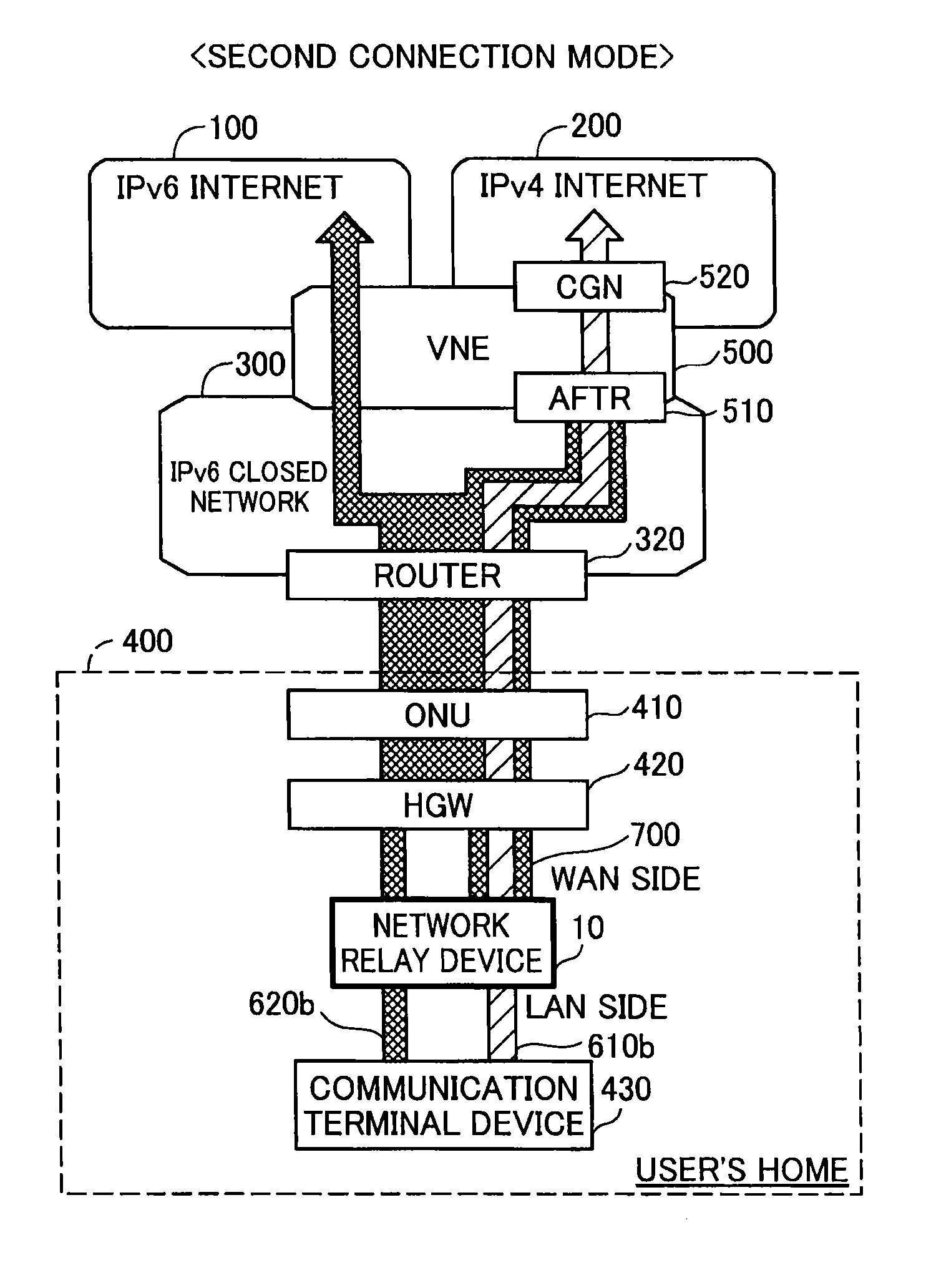
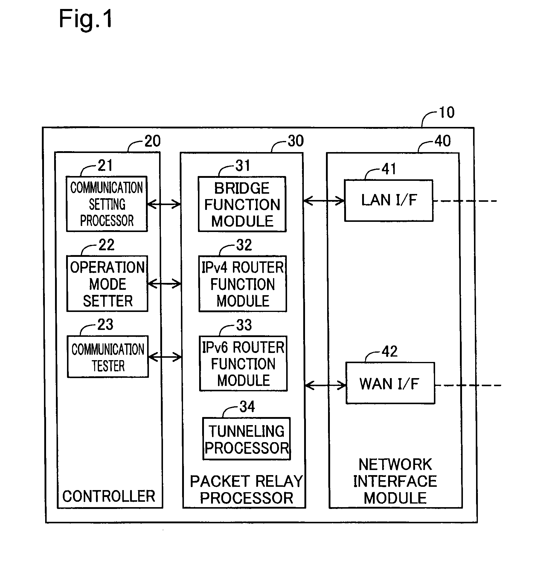
[0020]FIG. 1 is a diagram illustrating the general configuration of a network relay device 10 according to one embodiment of the disclosure. The network relay device 10 is configured to relay a data frame on a second layer (layer 2) of an OSI (Open Systems Interconnection) reference model. The network relay device 10 is also configured to relay a data packet on a third layer (layer 3). The network relay device 10 is connected with a communication terminal device such as a personal computer, to relay a packet with the communication terminal device as a source and a packet with the communication terminal device as a destination. The network relay device 10 supports both Internet Protocol version 4 (IPv4) and Internet Protocol version 6 (IPv6) as the layer 3 protocol.

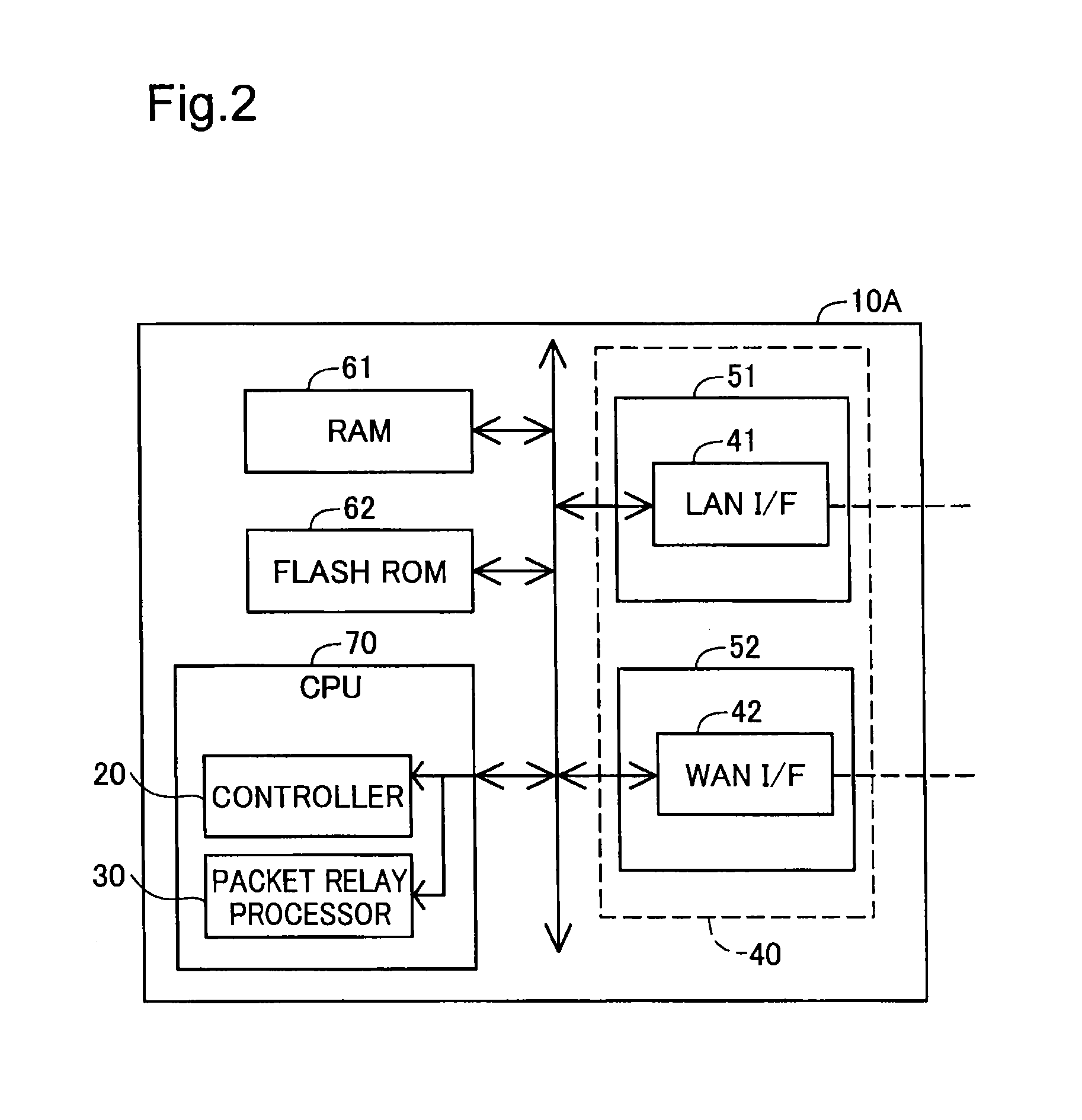
[0021]The network relay device 10 includes a controller 20, a packet relay processor 30 and a network interface 40. According to this embodiment, the respective functions of the c...

second embodiment

B. Second Embodiment

[0101]FIG. 10 is a flowchart showing a procedure of operation mode setting process according to a second embodiment. A network relay device of the second embodiment has similar configuration to that of the network relay device 10 of the first embodiment, and the like components are shown by the like numerals and are not specifically described here in detail. An operation mode setting process of the second embodiment differs from the operation mode setting process of the first embodiment shown in FIG. 7 by addition of steps S121 and S122. Otherwise the procedure of the operation mode setting process of the second embodiment is similar to the procedure of the operation mode setting process of the first embodiment, and the like steps are shown by the like step numbers and are not specifically described here in detail. A tunneling availability checking process and a communication setting process performed in the second embodiment are identical with the corresponding ...

modification 1

C1. Modification 1

[0106]The configuration of the network relay device 10 according to the above embodiment is only illustrative and may be modified in various ways. For example, the network relay device 10 and the communication terminal device 430 are directly connected with each other by a network cable in the above embodiment, but the disclosure is not limited to this configuration. The network relay device 10 and the communication terminal device 430 may be connected with each other, for example, via a layer 2 switch.

[0107]In another example, the LAN I / F 41 is provided as the function module that can serve as a wired LAN interface in the above embodiment but may be provided as a function module that can serve as a wireless LAN interface instead of the wired LAN interface. For example, IEEE 802.11a / b / g / n / ac may be employed for such a wireless LAN interface. In an application which employs the function module that can serve as the wireless LAN interface for the LAN I / F 41, the netw...


PUM


Abstract

An electronic device that relays an Internet Protocol (IP) packet compliant with one of a plurality of IP versions includes circuitry configured to process the IP packet in each of a first mode operating as a router and a second mode operating as a bridge; and set, as a mode of the electronic device, one of the first mode or the second mode, based on which of the plurality of IP versions the IP packet to be processed is compliant with.

Description

CROSS-REFERENCE TO RELATED APPLICATIONS[0001]The present application claims priority from Japanese Patent Application No. 2014-16797 filed on Jan. 31, 2014 and Japanese Patent Application No. 2014-229729 filed on Nov. 12, 2014, the entirety of disclosure of which is hereby incorporated by reference into this application.TECHNICAL FIELD[0002]The disclosure relates to relay of an Internet Protocol (IP) packet.BACKGROUND ART[0003]Addresses specified in Internet Protocol version 4 (IPv4) (IPv4 addresses) have conventionally been used in communication via the Internet, and depletion of newly allocatable IPv4 addresses has recently become a problem. Accordingly, introduction of Internet Protocol version 6 (IPv6) which is allowed to allocate a greater number of addresses has been started, and various software (for example, application programs) and hardware (communication terminals such as personal computer and network relay devices such as router device) compatible with IPv6 have been pro...

Claims


Application Information

Patent Timeline
IPC IPC(8): H04L12/56H04L29/06H04L12/781H04L45/741H04L45/52
CPCH04L45/52H04L69/167H04L45/741
Inventor INADA, TETSUYA
Owner BUFFALO CORP LTD
Why Eureka
Try Eureka