Eureka AIR delivers breakthrough ideas for toughest innovation challenges, trusted by R&D personnel around the world.

Solar cells and methods of fabrication thereof

Active Publication Date: 2015-08-13
PICASOLAR
View PDF2 Cites 5 Cited by
  • Summary
  • Abstract
  • Description
  • Claims
  • Application Information

AI Technical Summary

Benefits of technology

This patent describes a method for making solar cells more efficiently. The method involves depositing a layer of material called a passivation layer on the solar cell, which then has a grid line deposited on it. The passivation layer is annealed to deactivate the electrical activity of a dopant in one part of the cell (the first portion), while the grid line is annealed to form an electrical contact on the other part of the cell (the second portion). By doing this, the efficiency of the solar cells is improved. The method may be adjusted to control which part of the cell the dopant's activity is deactivated.

Problems solved by technology

High concentration of the active dopants at the surface of the emitter creates high surface recombination velocities.
High surface recombination velocity limits open-circuit voltage (Voc) and short-circuit current (Jsc) directly limiting the conversion efficiency of the solar cell.
All conventional selective emitter techniques require complicated alignment processing and have generally low throughput.
Such high sheet resistances cause a lot of power loss, so that conventional selective emitters require up to 50% more grid lines than the homogeneous emitter.
Because the grid metallization typically contains silver, this is a very expensive requirement.

Method used


Image

  • Solar cells and methods of fabrication thereof
  • Solar cells and methods of fabrication thereof
  • Solar cells and methods of fabrication thereof

Examples


Embodiment Construction

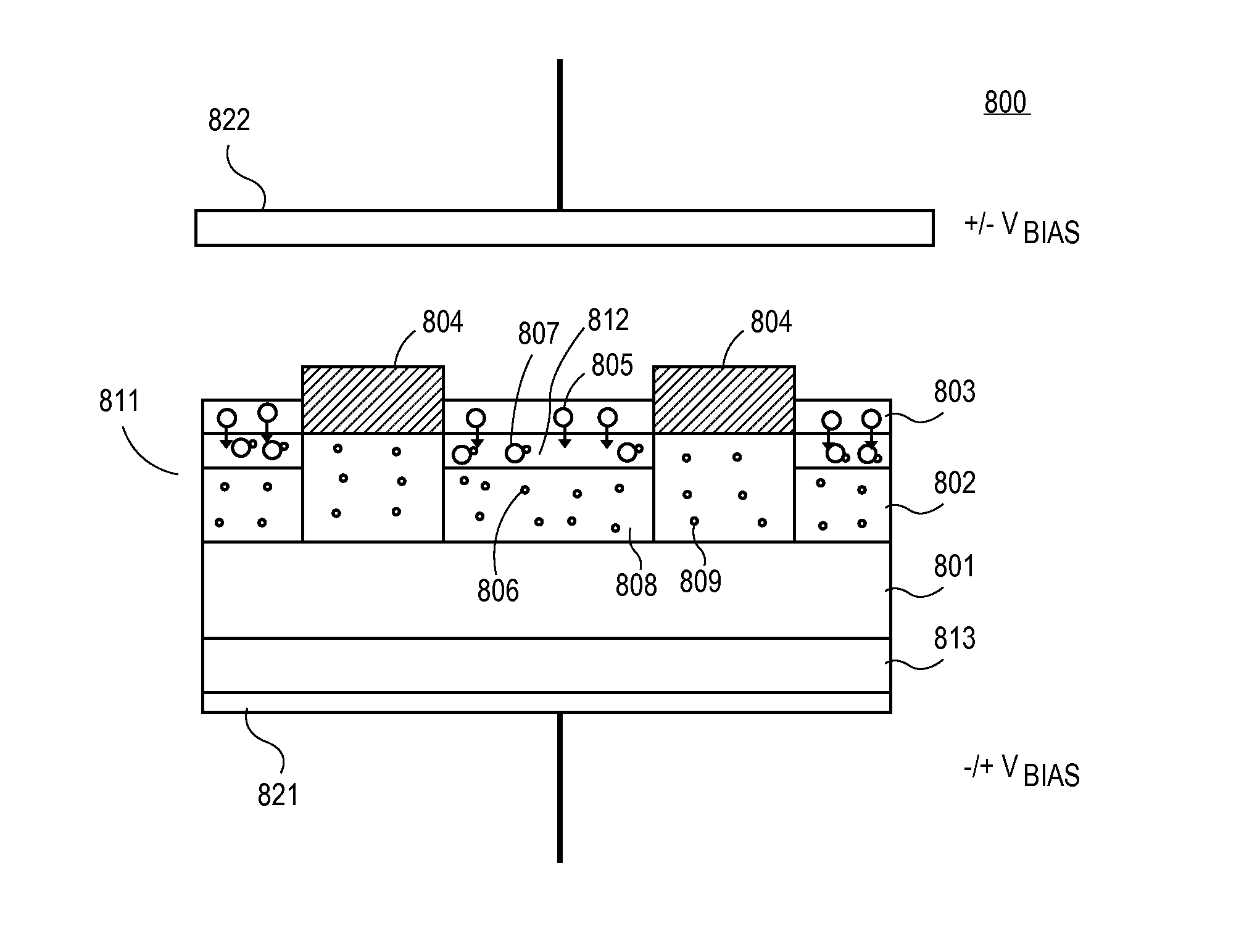
[0082]Methods and apparatuses to manufacture solar cells are described herein. In the following description, numerous specific details are set forth, such as specific process flow operations, in order to provide a thorough understanding of embodiments of the present invention. It will be apparent to one skilled in the art that embodiments of the present invention may be practiced without these specific details. In other instances, well-known fabrication techniques, such as semiconductor deposition techniques are not described in detail in order to not unnecessarily obscure embodiments of the present invention. Furthermore, it is to be understood that the various embodiments shown in the Figures are illustrative representations and are not necessarily drawn to scale.

[0083]In an embodiment, a passivation layer is deposited on a first portion of a region of the solar cell. A grid line is deposited on a second portion of the region. The passivation layer is annealed at a first temperatu...


PUM


Abstract

A passivation layer is deposited on a first portion of a region of the solar cell. A grid line is deposited on a second portion of the region. The passivation layer is annealed to drive chemical species from the passivation layer to deactivate an electrical activity of a dopant in the first portion of the region of the solar cell.

Description

TECHNICAL FIELD[0001]Embodiments of the present invention are related to the field of renewable energy and, in particular, to solar cells and methods of fabrication thereof.BACKGROUND[0002]Generally, solar cells are known as devices that convert solar radiation into electrical energy. Typically, solar cells are fabricated on a semiconductor substrate using semiconductor processing techniques to form a p-n junction near a surface of the substrate. Solar radiation incident upon the surface of the substrate creates electron and hole pairs in the bulk of the substrate. The electron and hole pairs migrate to p-doped and n-doped regions in the substrate, thereby generating a voltage differential between the doped regions. The doped regions are coupled to metal contacts on the solar cell to direct an electrical current from the cell to an external circuit coupled thereto. Radiation conversion efficiency is an important characteristic of a solar cell as it is directly related to the solar c...

Claims


Application Information

Patent Timeline
IPC IPC(8): H01L31/0216H01L31/0224H01L31/18
CPCH01L31/02167H01L31/02168H01L31/022433H01L31/1868H01L31/1864H01L31/068Y02E10/547Y02P70/50H01L31/0392Y02E10/50
Inventor SHUMATE, SETH DANIELHUTCHINGS, DOUGLAS ARTHURMOHAMMED, HAFEEZUDDINYOUNG, MATTHEWLITTLE, SCOTT
Owner PICASOLAR
Why Eureka
Eureka Blog
Learn More