Fluid homogenizer system for gas segregated liquid hydrocarbon wells and method of homogenizing liquids produced by such wells

a technology of gas segregation and hydrocarbon wells, which is applied in the direction of liquid degasification, separation process, and borehole/well accessories, etc., can solve the problems of destroying the well, destroying the surface facilities and related systems, and killing the well from flowing naturally, so as to reduce the hydrostatic head in the flow and increase the lift

Active Publication Date: 2015-08-20
SAUDI ARABIAN OIL CO
View PDF8 Cites 44 Cited by
  • Summary
  • Abstract
  • Description
  • Claims
  • Application Information

AI Technical Summary

Benefits of technology

[0011]The present invention relates to a system and method for improving the flow characteristics in such gas slugging wells. In particular, the method of the present invention passively separates the slugged gas from the fluid mix downhole, and then redirects the gas portion to a holding location in the form of an annulus, where the separated gas is then reinjected into the liquid column in a controlled method at a downstream location for the purpose of improving the homogeneity and flow characteristics of the production fluid. The injection of gas bubbles provides added lift to the liquid production, while improving the flow characteristics and reducing the risk of a “killed well”. This procedure prevents the upset of the surface facilities, and increases the flow rate over that of a slug-flow regime.
[0012]The system of the present invention consists first of a means to separate slug or segregate gas from the fluid flow downhole, then to collect the segregated gas, and then to provide a controlled means for injecting the gas back into the liquid stream, such that the injected gas is more uniformly and homogeneously distributed through the liquid, thereby improving the flow characteristics of the liquid / gas medium.
[0024]It is also envisioned, that under certain conditions, an optional compressor can be accumulated in the annulus between the gas / liquid separation device and the annular sealing packer. The compressor can thereby provide additional pressure, if needed, to the separated gas positioned in the annulus, to assist re-entry of the gases into the production tubing. Moreover, if required, an electric submersible pump (“ESP”), can be positioned in the production flow tube below the point of re-injection of the fine gas bubbles, or in proximal relation thereto, to assist fluid production flow.
[0025]The system and method of the present invention not only eliminates the gas slugs which often inhibit well production, but also re-introduces the gas into the flow upstream via an injection device, thereby reducing the hydrostatic head in the flow, while providing additional lift to the output of the well.

Problems solved by technology

As the well turns vertically at a heel portion and continues upwardly to the surface, the segregated gas will have a tendency to form large gas slugs in the liquid medium and possibly risk killing the well due to slugging flow, and upsetting the surface facilities and related systems.
At the heel of the well, the gas and liquids may be significantly segregated such that the segregated gas may be in slug form and provide an imbalance in the fluid lift, thereby potentially killing the well from flowing naturally.
In addition, the gas slugs passing through surface equipment can upset the surface facilities and related systems, thereby making it difficult to efficiently process the produced liquid hydrocarbons from the well.
Although such prior art systems represent attempts to separate gas from liquid downhole, the problems associated with gas slugging continues to hamper production in such gaseous slug-laden wells.

Method used


Image

  • Fluid homogenizer system for gas segregated liquid hydrocarbon wells and method of homogenizing liquids produced by such wells
  • Fluid homogenizer system for gas segregated liquid hydrocarbon wells and method of homogenizing liquids produced by such wells
  • Fluid homogenizer system for gas segregated liquid hydrocarbon wells and method of homogenizing liquids produced by such wells

Examples


first embodiment

A First Embodiment

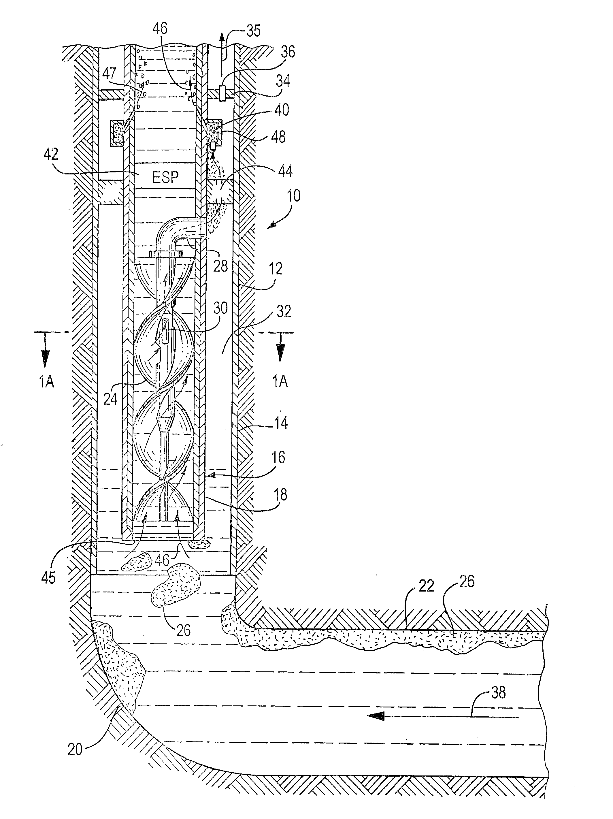
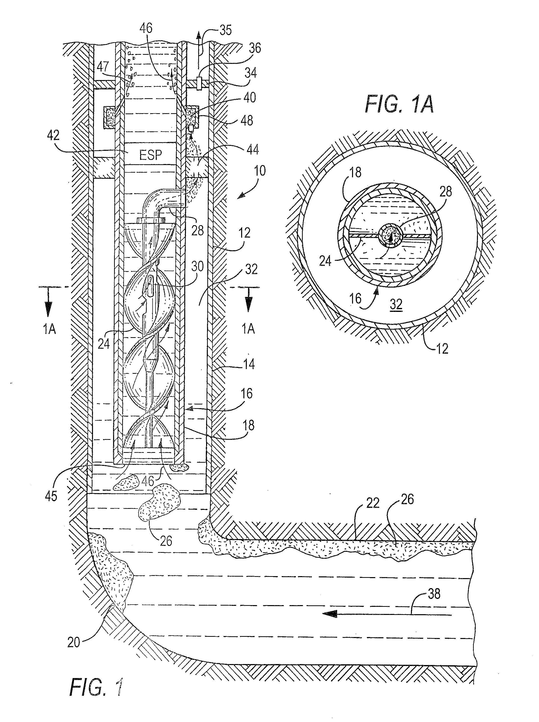
[0051]Referring initially to FIG. 1, there is illustrated a system 10 constructed according to one preferred embodiment of the invention. According to this embodiment, the system 10 is installed in vertical wellbore 12 of a well, the wellbore 12 being lined with casing 14.

[0052]The system 10 includes a passive gas / liquid separation device 16 in the form of flow tube 18 which is located above the heel portion 20 of the well, which heel portion 20 connects the vertical wellbore 12 with a generally horizontal borehole 22.

[0053]The fluid flow 38 (i.e., liquid, gas slugs and water) from horizontal borehole 22 reaches the heel 20 as shown, and rises upwardly in the vertical casing where it meets the flow tube 18. At this location, the fluid enters the vertical flow tube 18 and proceeds upwardly along the spiral path defined by spiral baffle 24.

[0054]The system of FIG. 1 includes one preferred form of gas / liquid separation device 16 in the form of spiral baffle, or auger ...

second embodiment

A Second Embodiment

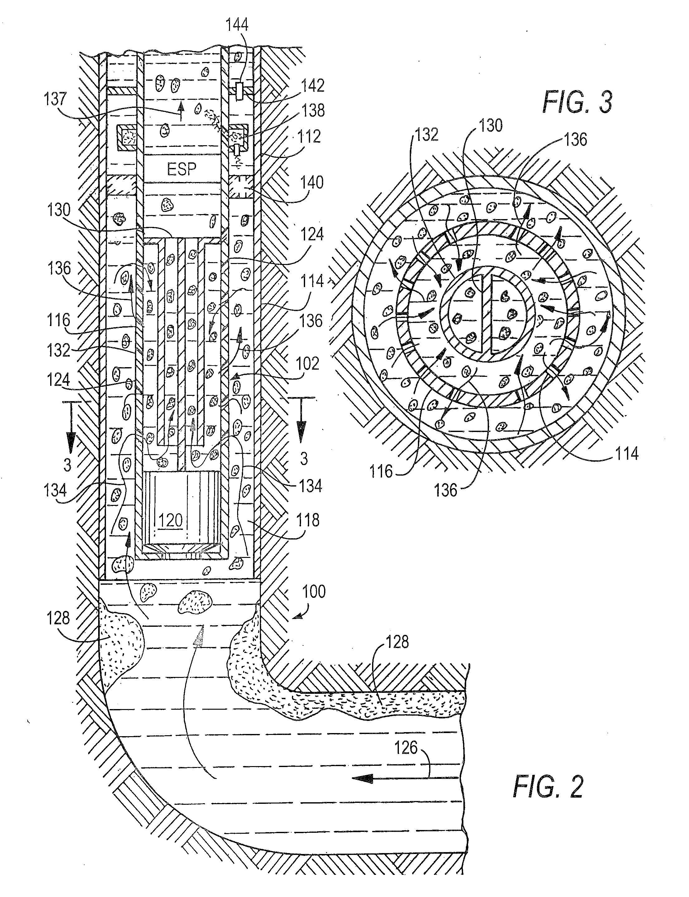
[0074]Referring now to FIGS. 2-3, there is illustrated an alternative embodiment 100 of the inventive system, which includes passive gas / liquid separation device 102 in the form of flow tube 116. Wellbore 112 is lined with casing 114 in which flow tube 116 is positioned to form annulus 118 with casing 114, as shown. In this embodiment, flow tube 116 is closed at its lowermost end by plug 120. In principle, the operation of the embodiment of FIGS. 2 and 3 differs from the previous embodiment, but the objectives and results are similar. The tortuous apertures 124 in flow tube 116 receive and direct the liquid 126 containing gaseous slugs 128 into the flow tube 116 as shown, while the major portion of the gaseous medium is permitted to move upwardly into annulus 118 via apertures 124. The flow tube 116 includes a central separator baffle 130 for further assistance and guidance of the liquid medium, the central baffle 130 being surrounded by circular baffle 132 as sho...

third embodiment

A Third Embodiment

[0077]Referring now to FIG. 4, there is illustrated an enlarged cross-sectional view of a lowermost portion of yet another alternative embodiment 200 of the invention, in which the flow from a horizontal borehole of the well enters the tube 210, which is closed at its lowermost end by integrally formed base plate 212, the flow tube 210 including apertures 214 which create respective tortuous paths as depicted by arrows 216, for separation of the gas from the liquid. This path causes the gas slugs to be broken up and to be stripped from the liquid while entering the annulus 218 formed between the flow tube 210 and the casing 220. The gas is thus stripped from the liquid / gas mix and then permitted to accumulate in the annulus 218, where it is reinjected into the flow tube 210 at the upper end (not shown in FIG. 4) in the same manner as described in connection with the previous embodiments.

[0078]In all other respects, the operation and the remaining structure and func...


PUM

PropertyMeasurementUnit
pressureaaaaaaaaaa
gaseous pressureaaaaaaaaaa
homogeneityaaaaaaaaaa

Abstract

A system and method for improving the flow characteristics of gaseous slug-laden liquid hydrocarbon wells, particularly from horizontal, of similar boreholes. The invention provides a system and method which essentially homogenizes the liquid and the gas, utilizing a unique flow tube arrangement and a sequence of steps by first breaking up and separating the slugged gas from the liquid at a first location, and then gathering it into holding location—i.e., an annulus section—where it is re-introduced in controlled amounts into the liquid downstream of the first location. The gas is re-introduced into the liquid flow in such pre-determined and controlled quantities as to promote better pressure and flow characteristics of the hydrocarbon liquid product. Various alternative gas / liquid separation devices are incorporated into the system of the invention, which devices may be located either in a vertical wellbore or a horizontal wellbore, depending upon the particular well characteristics. Optionally, an electric submersible pump may be incorporated where needed to assist the mixed production flow toward surface. A compressor may optionally be provided in the gaseous holding location, where needed. An apparatus for homogenizing production fluid from an oil well having one or more horizontal bores is also disclosed.

Description

BACKGROUND OF THE INVENTION[0001]1. Field of the Invention[0002]The present invention relates to a system and method for homogenizing production fluid from an oil well having gas slugging, for the purpose of improving the flow characteristics of the well.[0003]2. Description of the Related Art[0004]In long horizontal liquid wells with a gas cap, the gas may influx into the wellbore. As it travels the horizontal length, the gas tends to segregate and migrate upwardly from the liquid, collecting and forming high pressure gas bubbles generally referred to as gas slugs. As the well turns vertically at a heel portion and continues upwardly to the surface, the segregated gas will have a tendency to form large gas slugs in the liquid medium and possibly risk killing the well due to slugging flow, and upsetting the surface facilities and related systems.Horizontal Wells[0005]In long horizontal wells, the fluid flow has a tendency to segregate, with lighter fluids and gas drifting toward the...

Claims


Application Information

Patent Timeline
Patent Type & Authority Applications(United States)
IPC IPC(8): E21B43/40E21B33/12E21B41/00B01F3/04E21B43/12B01F23/00
CPCB01D19/0042E21B43/122E21B43/38B01F23/024B01F23/2323B01F25/43141B01F25/45211B01F2101/40E21B43/128E21B33/12E21B43/16
Inventor ROTH, BRIAN A.LASTRA, RAFAEL
Owner SAUDI ARABIAN OIL CO
Why Eureka
Try Eureka