Pump

a technology of pump and pump body, applied in the direction of pump control, positive displacement liquid engine, motor parameter, etc., can solve the problems of low pressure and irregular flow rate, inability to deal with corrosive reagents, irregular output flow rate, etc., and achieve constant level

Inactive Publication Date: 2015-08-27
VAPORTEC
View PDF4 Cites 12 Cited by
  • Summary
  • Abstract
  • Description
  • Claims
  • Application Information

AI Technical Summary

Benefits of technology

[0011]Adjusting the operating speed according the detected pressure provides a more accurate and more rapid feedback than feedback based on flow rates and eliminates the need for mass flow sensing which can be highly problematic with corrosive solutions.
[0067]Furthermore, the limited influence of the feedback from the pressure sensor in the slow portions of the lookup table can provide significant immunity of the pump control to external pressure disturbances, such as those caused by another pump operating further downstream.

Problems solved by technology

However, this pumping can be the source of problems, particularly on the laboratory scale, for example where corrosive reagents or reagents with a high concentration of particulates are used in the reaction.
These pumps have typically been unable to deal with corrosive reagents, have operated at relatively low pressure and have had irregular output flow rate.
By selecting the correct material for the reagent being pumped the tubes are able to cope with acids, bases and organic solvents without corrosion or physical deterioration, but this does not address the problems of low pressure and irregular flows.
Syringe pumps are used, but these are obviously limited in their capacity, even if paired, which requires change over in order to provide a continuous supply of reagent.
However, the pistons in such pumps require non-return valves to prevent the reagent from being forced back into the supply rather than out to the reaction chamber and such valves do not cope well with precipitates, air bubbles in the reagent or immiscible liquids.

Method used


Image

  • Pump
  • Pump
  • Pump

Examples


Embodiment Construction

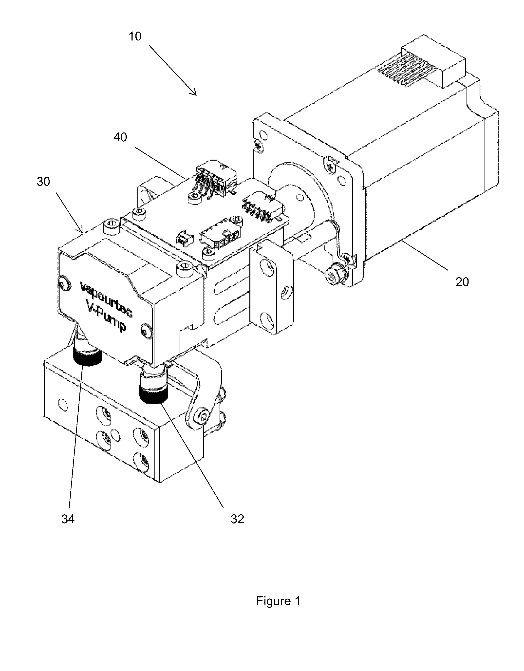
[0078]FIG. 1 shows a perspective view of a peristaltic pump 10 according to an embodiment of the present invention. The pump has a stepper motor 20, a pump unit 30 and circuit board 40. Further control circuitry and connections, discussed in more detail below, connect the circuit board 40 and the stepper motor 20 and control the operation of the pump 10.

[0079]The pump unit 30 is arranged to pump reagents from inlet 34 out through outlet 32. The inlet 34 is generally connected, in use, to a source of a reagent, such as a storage vat or bottle, or to the output of an earlier reaction system. The outlet 32 is generally connected, in use, to a reaction chamber for conducting flow chemistry. Suitable sources of reagents and reaction chambers are well known in the art and will not be described further here.

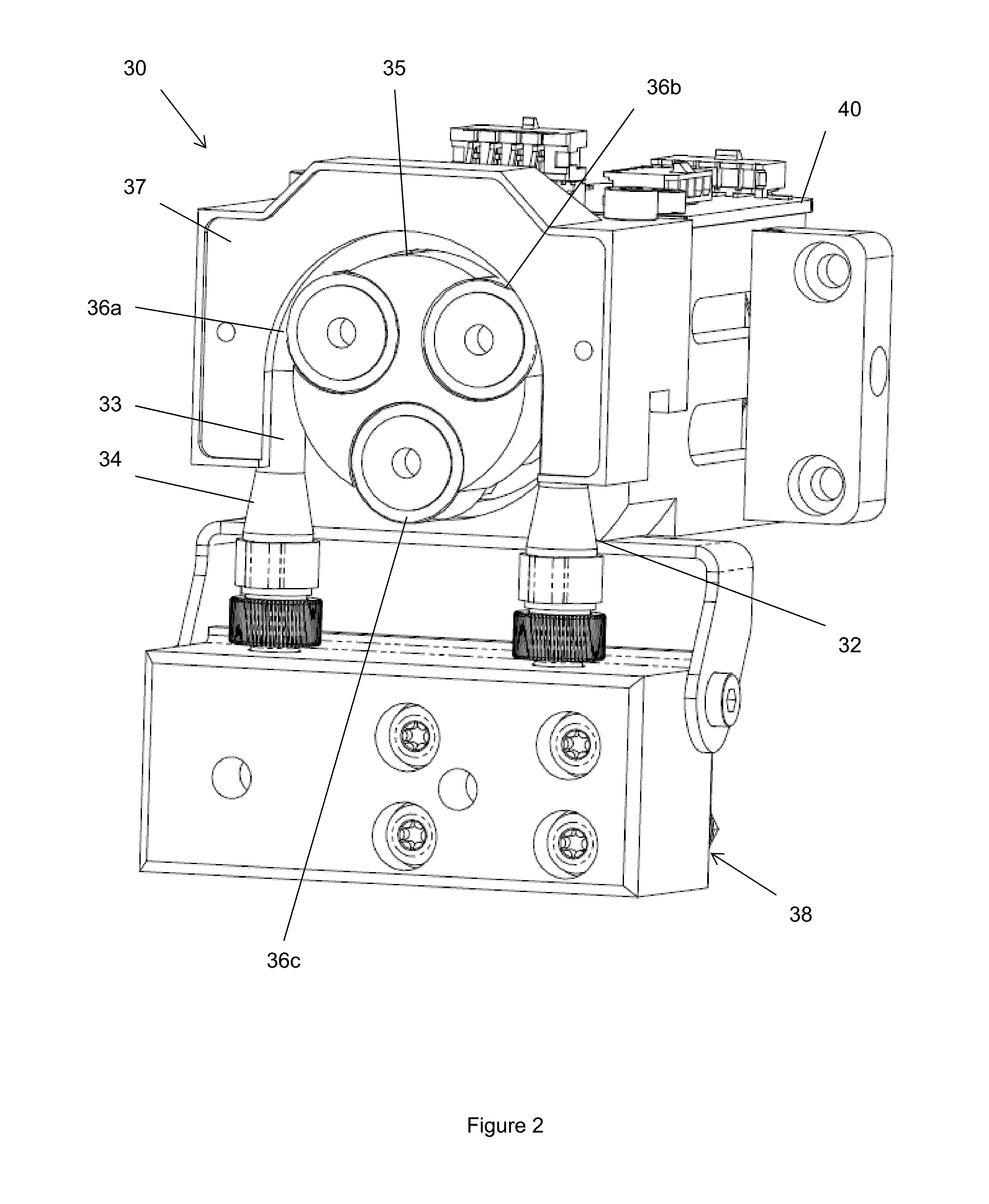
[0080]FIG. 2 shows the detail of the pump unit 30 with the front cover removed. The pump unit consists of a standard, albeit high quality and rugged, peristaltic pump configuration in w...


PUM


Abstract

Provided is a pump and a method of controlling a pump. The pump and method are particularly for use in dispensing reagents, for example in flow chemistry, and more particularly on a laboratory scale. The pump aims to provide a substantially constant output flow of fluid. The pump comprises: a motor; a peristaltic pump having a rotor driven by the motor; a pressure sensor monitoring the pressure of the pumped fluid downstream of the pump; and a control unit which controls the motor by adjusting the standard operating speed of the motor according to the pressure detected by the pressure sensor, such that the pump operates continuously at a rate set by an operator. Embodiments of the pump make use of lookup tables to determine a desired position of the pump rotor at each point in the cycle with the entry point into the lookup table being determined by the feedback from the pressure sensor. Long term changes in the performance of the pump can also be accounted for by changing the entry in the lookup table which is consulted.

Description

FIELD OF THE INVENTION[0001]The present invention relates to a pump and a method of controlling a pump. The invention is particularly, but not exclusively, concerned with a pump for use in flow chemistry or for dispensing reagents and a method of controlling such a pump.BACKGROUND OF THE INVENTION[0002]Flow chemistry is a process whereby a chemical reaction is run in a continuously flowing stream rather than in one or more batches. Although long used in manufacturing processes on a large scale, flow chemistry has only recently been developed in the research / laboratory environment.[0003]A key characteristic of flow chemistry is the need to pump liquids to and normally through reaction vessels. However, this pumping can be the source of problems, particularly on the laboratory scale, for example where corrosive reagents or reagents with a high concentration of particulates are used in the reaction.[0004]Where reagents contain particulates existing pumps used in laboratory scale flow c...

Claims


Application Information

Patent Timeline
Patent Type & Authority Applications(United States)
IPC IPC(8): F04B49/20F04B43/12
CPCF04B43/12F04B49/20F04B43/1238F04B43/1253F04B49/065F04B49/08F04B2203/0209F04B2205/05
Inventor GUTHRIE, DUNCANCLARKSON, ADRIAN
Owner VAPORTEC
Why Eureka
Try Eureka