Integrated electronic design automation system
a technology of electronic design and automation system, which is applied in the direction of configuration cad, total factory control, instruments, etc., can solve the problem that there are no fully integrated systems known to exist to provide dedicated end-to-end design
- Summary
- Abstract
- Description
- Claims
- Application Information
AI Technical Summary
Benefits of technology
Problems solved by technology
Method used
Image
Examples
examples
[0052]NAME=VCC—1.8 &MATCH=VCC—1.8&TYPE=R&QTY=1&IDX=1&LVL=1.8&WIRE=1&ROUTE=1[0053]NAME=I2C&MATCH=I2C* &TYPE=R&QTY=0&IDX=1&LVL=1.8 &WIRE=1 &ROUTE=1[0054]NAME=VCC—5.0&MATCH=VCC—5.0&TYPE=P&QTY=1000&IDX=1&LVL=5.0&WIRE=1&ROUTE=1
[0055]Nets:[0056]Nets connected to an EIS type provide should be named according to the following template:[0057]first-bus-name_first-function& . . . &last-bus-name_last-function
example
[0058]GPIO0_GPIO0&UART1_TX[0059]GPIO1_GPIO1&UART1_RX
[0060]The corresponding bus names would be:[0061]NAME=GPIO0 . . . IDX=1[0062]NAME=UART 1 . . . IDX=2[0063]NAME=GPIO1 . . . IDX=1
[0064]The following pseudo code represents a further level of detail of this invention.
[0065]The invention is expected to find a number of applications. +++
1) The Small Business Customer
[0066]COM customers typically fall into two categories, the first being a hobbyist or researcher building a prototype. The researcher may purchase a small number of COMs and expansion boards from Gumstix and modify them to meet specific needs. In many cases, the researcher, receiving outside funding for the product may become the second category, the volume customer. Volume customers may be expected to continue to buy COMs but design and manufacture a custom expansion board that meets their exact mechanical and electrical requirements. This represents a major challenge for businesses without PCB design expertise, and a lost...
process example
1) Scenario
[0069]A user wants to build a computer for automobiles that can track position, monitor the vehicle health, and serve as a media center.
[0070]Requirements:[0071]Overo COM[0072]12V Power Input[0073]CAN bus for monitoring and controlling automotive subsystems[0074]GPS for trip tracking and navigation[0075]HDMI output for a monitor
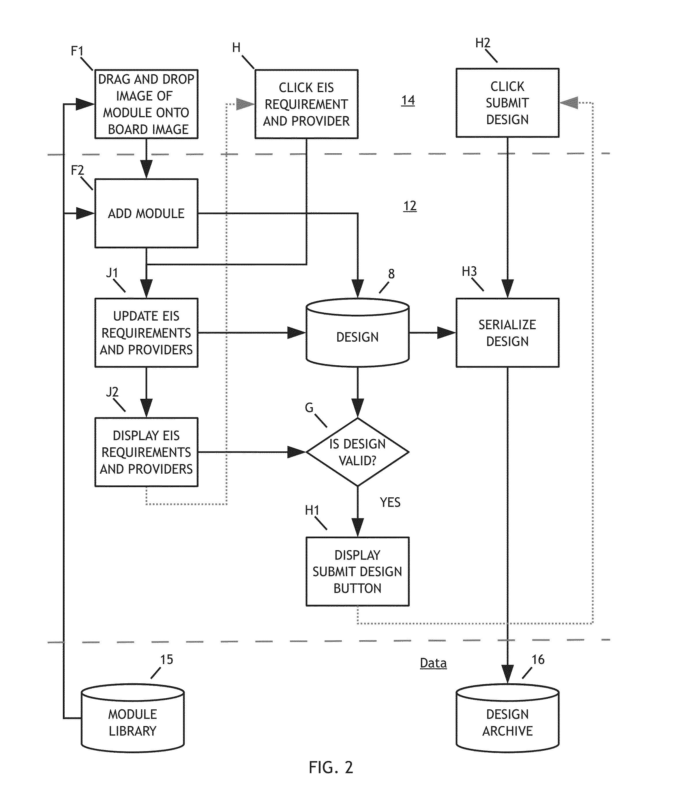
[0076]Design[0077]Create a user account at a website[0078]Select File ->New from the menu bar—A design area and module library will appear[0079]In the module library, click on the Processors category[0080]Drag an Overo COM onto the blank PCB in the design area[0081]Click on the Power category and drag 12V power onto the board[0082]Add remaining modules[0083]Modules highlighted in red have unsatisfied bus requirements, click on each for a list of modules that can fill the requirement. The designer may have to add additional modules from the library.[0084]Position the modules and resize the board to meet mechanical requirements. One can drag them int...
PUM
 Abstract
Description
Claims
Application Information
 - R&D
- Intellectual Property
- Life Sciences
- Materials
- Tech Scout
- Unparalleled Data Quality
- Higher Quality Content
- 60% Fewer Hallucinations
Browse by: Latest US Patents, China's latest patents, Technical Efficacy Thesaurus, Application Domain, Technology Topic, Popular Technical Reports.
© 2025 PatSnap. All rights reserved.Legal|Privacy policy|Modern Slavery Act Transparency Statement|Sitemap|About US| Contact US: help@patsnap.com


