
Power control device

a power control device and power supply technology, applied in the direction of power supply testing, process and machine control, instruments, etc., can solve the problems of equipment trip, frequency deviating from its nominal value, equipment maintenance is expensive, etc., to increase the frequency stability of the ac power grid and increase the rate of energy transfer

Active Publication Date: 2015-08-27
BIPCO SOFT R3
View PDF4 Cites 20 Cited by
  • Summary
  • Abstract
  • Description
  • Claims
  • Application Information

AI Technical Summary

Benefits of technology

[0009]In a specific and nonlimiting example of implementation, the power control device operates independently without external control input other than the AC frequency. This makes the installation and deployment of the system simple since there is no need to install a dedicated communication channel to carry commands to the device.
[0040]Under the fourth broad aspect, the invention yet provides a method for increasing the frequency stability of an AC power grid, wherein the AC power grid manifests a rate of frequency deviation as a result of an imbalance due to a power generation deficit, the method including providing a supplemental energy source that is connected to the AC power grid and subsequent the occurrence of the imbalance, increasing a rate of energy transfer from the supplemental energy source into the AC power grid at a rate that is equal or exceeds the rate of frequency deviation.

Problems solved by technology

However, the maintenance of this reserve capacity is an expensive proposition since the reserve constitutes a resource that cannot be effectively monetized by the utility company.
Any sudden changes in generation or load resulting in an imbalance between generation and load will lead to a frequency instability during which the frequency deviates from its nominal value.
Large frequency variations are undesirable because they could lead to equipment trip or even a system collapse.
The speed governor however has some inherent limitations.
In particular, it is slow to respond since it involves certain mechanical constraints.
When the AC power grid experiences a significant imbalance due to a power generation deficit, the kinetic energy will be tapped and converted in electricity to feed the load, thus compensating temporarily the power generation deficit.

Method used


Image

  • Power control device
  • Power control device
  • Power control device

Examples


Embodiment Construction

[0057]To facilitate the description, any reference numeral designating an element in one figure will designate the same element if used in any other figure. In describing the embodiments, specific terminology is used but the invention is not intended to be limited to the specific terms so selected.

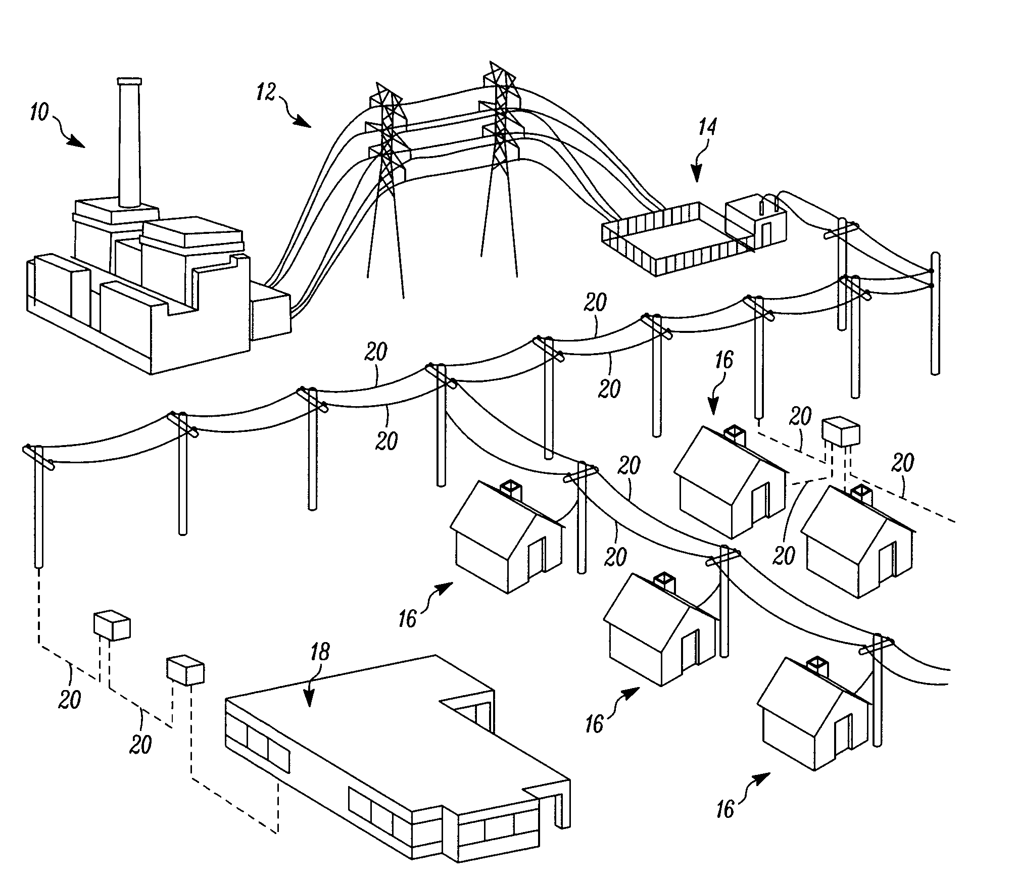
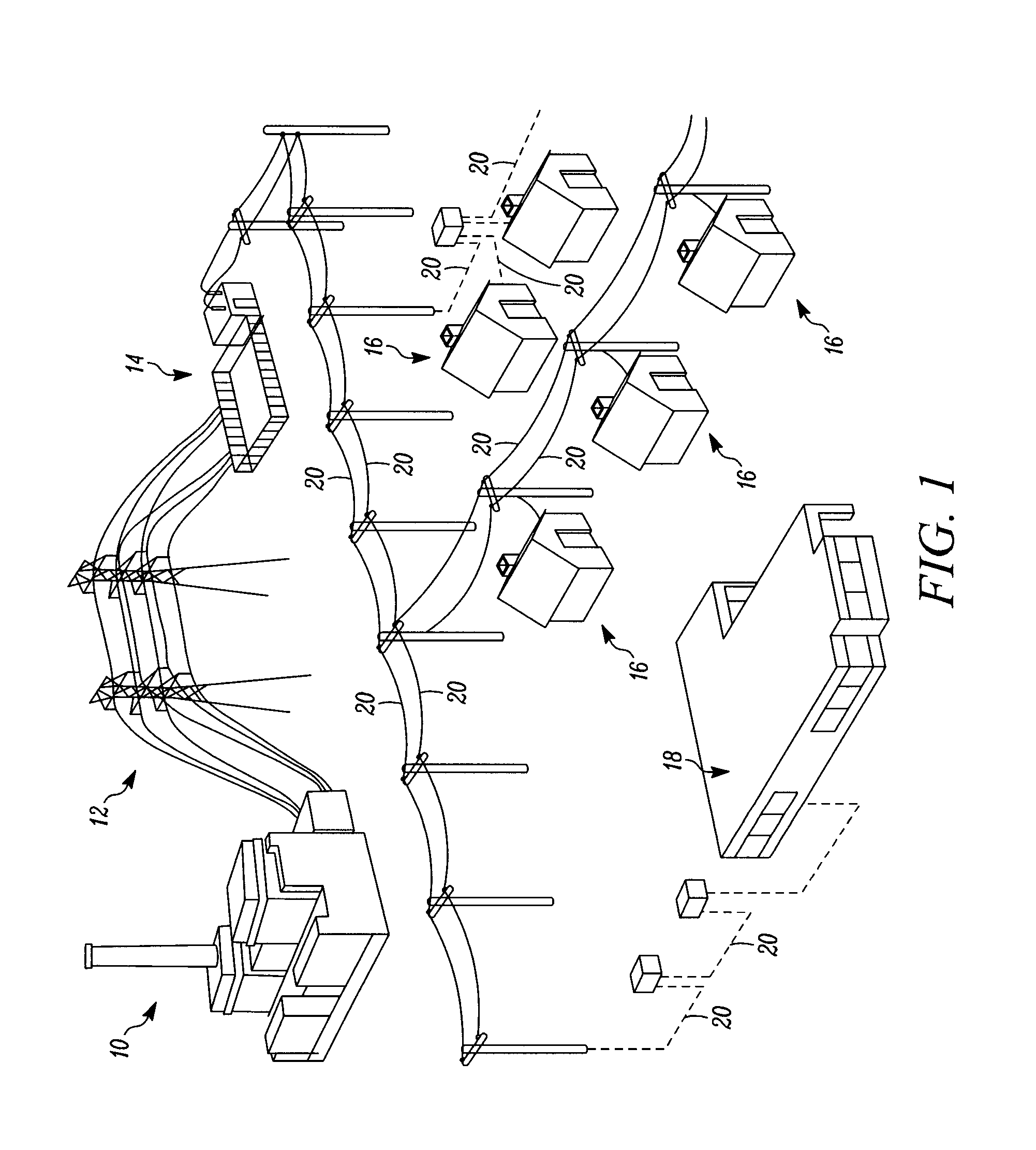
[0058]FIG. 1 shows an AC power grid. Electricity is generated at a power plant 10 and is transmitted over high voltage transmission lines 12 to a voltage down step station 14. The voltage down step station 14 lowers the electrical voltage (via transformers for example) such that it may be distributed to households 16 and industrial buildings 18 via residential distribution lines 20.

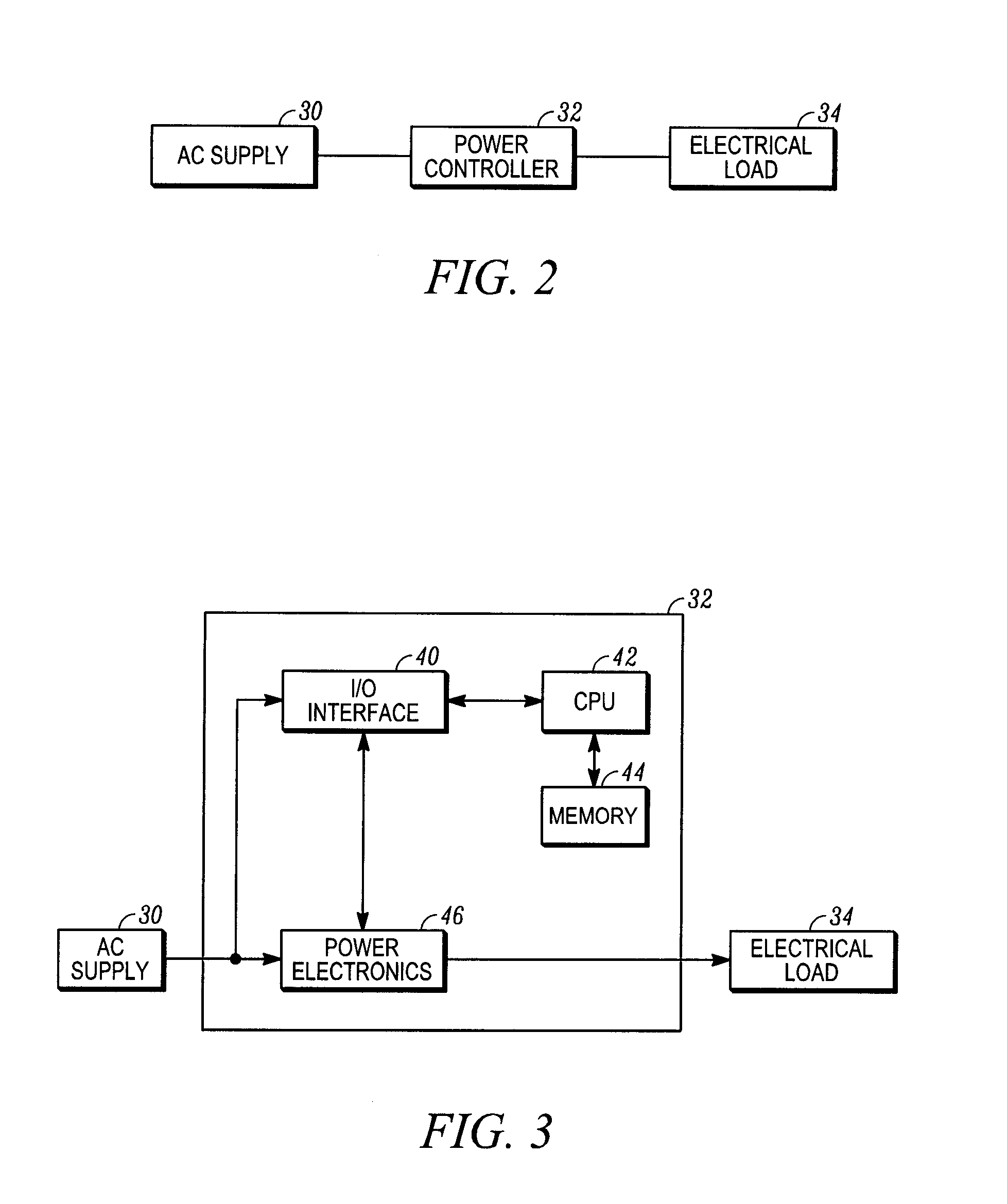
[0059]In a first example of implementation, the present invention provides a power controller 32 that can regulate the electrical load that household appliances or industrial equipment are allowed to consume. By using a sufficient number of such power control devices, a significant portion of the grid load is co...


PUM


Abstract

A power control device for use in an AC power grid for regulating an electrical power a load that is supplied by the AC power grid consumes. The power control device has a frequency sensing functional block for detecting a rate of deviation of the grid frequency from a nominal grid frequency and a logic functional block for performing a load shedding process during which the power the load consumes is reduced. The load shedding process is characterized by parameters, the logic functional block controlling one or more parameters of the load shedding process at least in part on the basis of the rate of deviation of the grid frequency.

Description

FIELD OF THE INVENTION[0001]The present invention relates to a controller for controlling the electrical power transferred between an AC power grid and an external device that is the electrical power consumed by a load connected to the power grid or injected in the power grid from a supplemental energy source. The invention also extends to control strategies for such power transfer functions. In a specific and non-limiting example of implementation, the invention can be used to improve the power grid frequency stability.BACKGROUND OF THE INVENTION[0002]To ensure the reliability of an electric power grid, the operator continually maintains a power reserve to compensate for a possible failure of electrical generation units. The power reserve is essentially an excess production capacity on standby. In normal conditions, the power generation units are run at less than 100% such that a degree of reserve power is always available. However, the maintenance of this reserve capacity is an ex...

Claims


Application Information

Patent Timeline
Patent Type & Authority Applications(United States)
IPC IPC(8): H02J3/12G01R31/42
CPCG01R31/42H02J3/12G05F1/70H02J2310/14H02J3/14Y04S20/222Y02B70/3225Y04S20/242Y02B70/30H02J3/00
Inventor TRUDEL, GILLESJASMIN, SIMONNORMANDIN, IRENE
Owner BIPCO SOFT R3
Learn More