Driving circuit and driving method thereof

Active Publication Date: 2015-08-27
DELTA ELECTRONICS INC
View PDF3 Cites 0 Cited by
  • Summary
  • Abstract
  • Description
  • Claims
  • Application Information

AI Technical Summary

Benefits of technology

The present invention relates to a driving circuit and method for a single-phase brushless DC fan. The objective is to reduce power consumption during operation at medium-low rotation speeds. The invention achieves this by changing the coupling arrangement of coils while the motor is operated at a medium-low rotation speed. This results in a lower power output, leading to power saving.

Problems solved by technology

However, when the rotation speed of the motor is adjusted down to the range of medium-low rotation speed, the unnecessary power loss will exist.

Method used


Image

  • Driving circuit and driving method thereof
  • Driving circuit and driving method thereof
  • Driving circuit and driving method thereof

Examples


Embodiment Construction

[0026]The present invention will be apparent from the following detailed description, which proceeds with reference to the accompanying drawings, wherein the same references relate to the same elements.

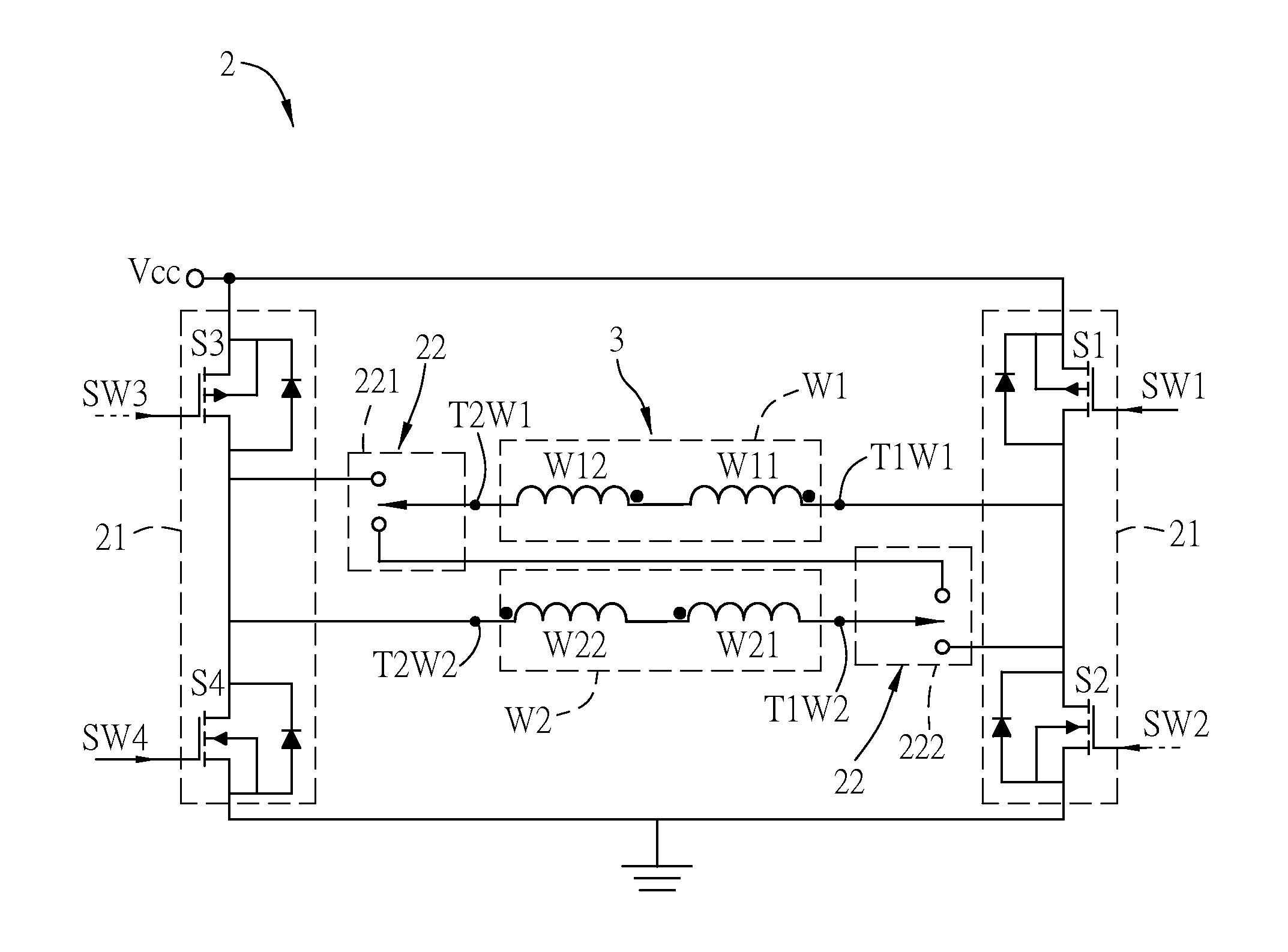
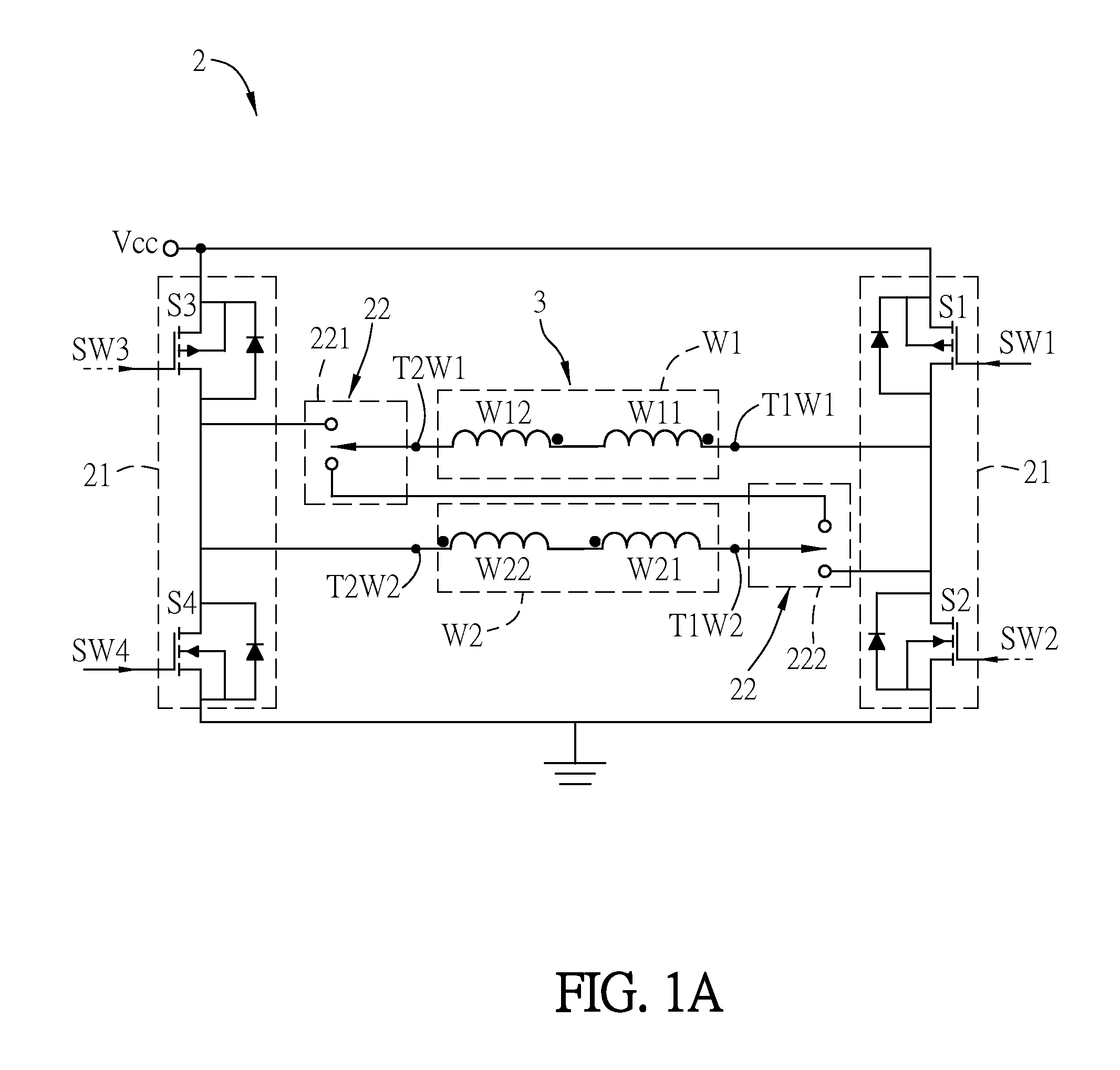
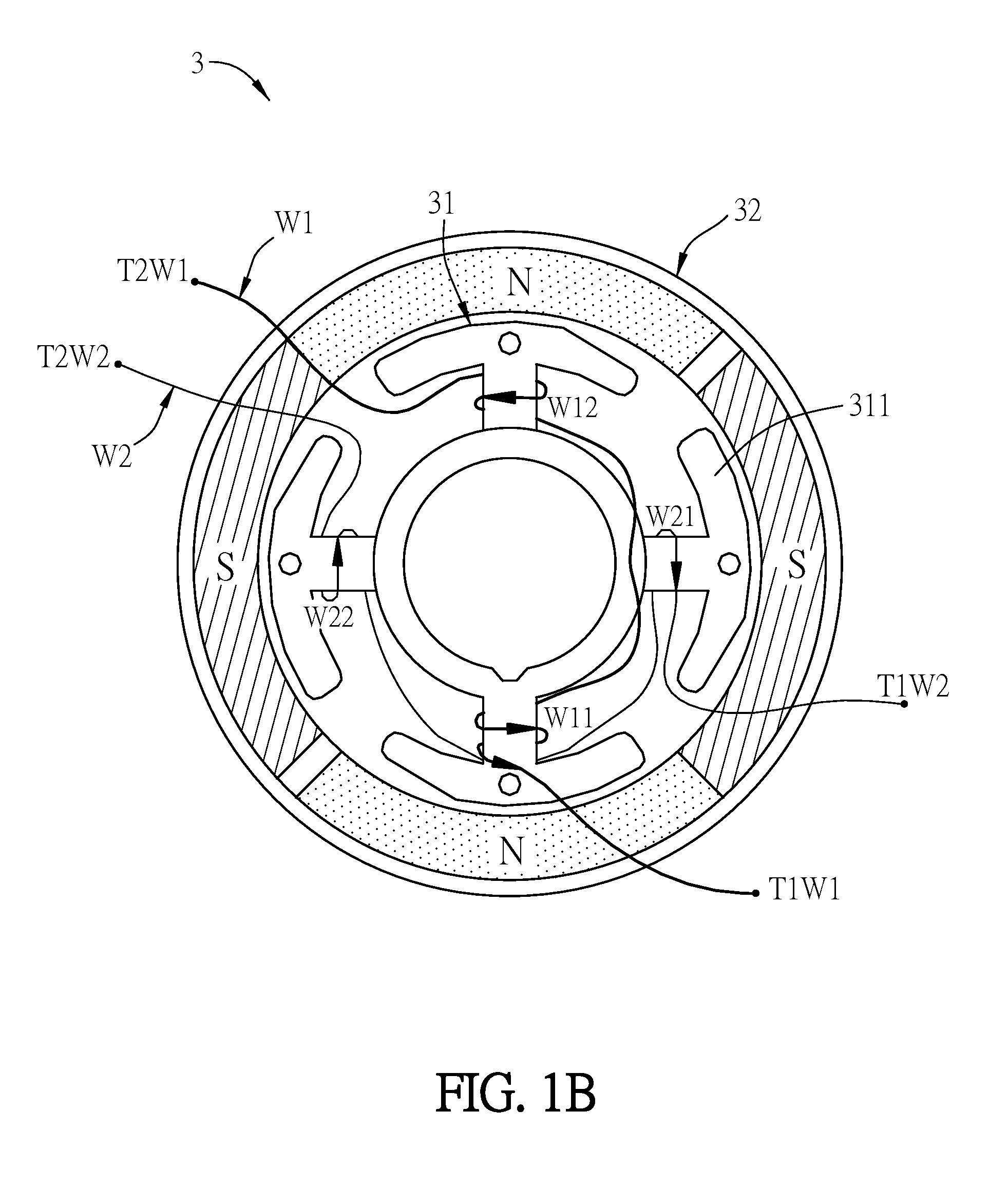
[0027]FIG. 1A is a circuit diagram of a driving circuit 2 for driving a motor 3 according to a preferred embodiment of the invention, FIG. 1B is a schematic diagram of the motor 3 of FIG. 1A, and FIG. 1C is a schematic diagram of a control unit C.

[0028]The motor 3 is a single-phase brushless DC motor and includes a stator structure 31, a rotor structure 32, a first coil W1 and a second coil W2. The rotor structure 32 is disposed around the outside of the stator structure 31. The first coil W1 and the second coil W2 are wound on a plurality of pole arms 311 of the stator structure 31 (the number of turns of the coils shown in the figures is for an illustration only), and are disposed corresponding to the magnet poles N and S of the rotor structure 32. In this embodiment, the motor 3 is...


PUM


Abstract

A driving circuit drives a motor containing a first coil and a second coil. The driving circuit includes a switching unit, an operation unit and a control unit. The switching unit receives a switching signal from the control unit for driving the motor. The control unit detects the rotation speed of the motor. When the rotation speed of the motor is greater than a predetermined rotation speed, the control unit outputs a first operation signal to the operation unit to couple the first terminals of the first and second coils and couple the second terminals of the first and second coils. When the rotation speed of the motor is less than or equal to the predetermined rotational speed, the control unit outputs a second operation signal to the operation unit to couple the second terminal of the first coil to the first terminal of the second coil.

Description

CROSS REFERENCE TO RELATED APPLICATIONS[0001]This Non-provisional application claims priority under 35 U.S.C. §119(a) on Patent Application No(s). 103105777 filed in Taiwan, Republic of China on Feb. 21, 2014, the entire contents of which are hereby incorporated by reference.BACKGROUND OF THE INVENTION[0002]1. Field of Invention[0003]The present invention relates to a driving circuit and a driving method thereof, and in particular, to a driving circuit of a single-phase brushless DC fan and a driving method thereof.[0004]2. Related Art[0005]Motors are a commonly used device for transforming electricity to mechanical energy. The motor has been applied to many products such as fans, optical disk drives, hard disk drives, optical devices, vehicle devices, computer apparatuses, appliances and mechanical apparatuses.[0006]As the progressive of technologies, the existing motors can provides high power outputs so as to operating at high speed. However, when the rotation speed of the motor ...

Claims


Application Information

Patent Timeline
IPC IPC(8): H02P6/00H02P7/00H02P6/08
CPCH02P6/008H02P2007/0005H02P7/00H02P6/085H02P6/26H02P25/188
Inventor TANG, CHUNG-HUNGLIN, CHIEN-SHENGCHIU, CHIN-FACHIU, CHUN-LUNG
Owner DELTA ELECTRONICS INC
Why Eureka
Try Eureka