Audio signal processing device

a signal processing and audio technology, applied in frequency response correction, electrical transducers, instruments, etc., can solve the problems of difficult to accurately calculate peak coordinates by clustering histograms, sound source separation effects by linear combination process in the system, and easy space reverberation, etc., to achieve the effect of higher accuracy

Active Publication Date: 2015-08-27
JVC KENWOOD CORP A CORP OF JAPAN
View PDF4 Cites 13 Cited by
  • Summary
  • Abstract
  • Description
  • Claims
  • Application Information

AI Technical Summary

Benefits of technology

[0013]According to the audio signal processing device, the audio signal processing method, and the audio signal pr

Problems solved by technology

However, reverberation can easily occur in a space such as an automobile which is narrowly closed, and the sound source separation effects by the linear combination process in the system disclosed in Japanese Unexamined Patent Application Publication No. 2006-197552 are limited.
Moreover, due t

Method used


Image

  • Audio signal processing device
  • Audio signal processing device
  • Audio signal processing device

Examples


first embodiment

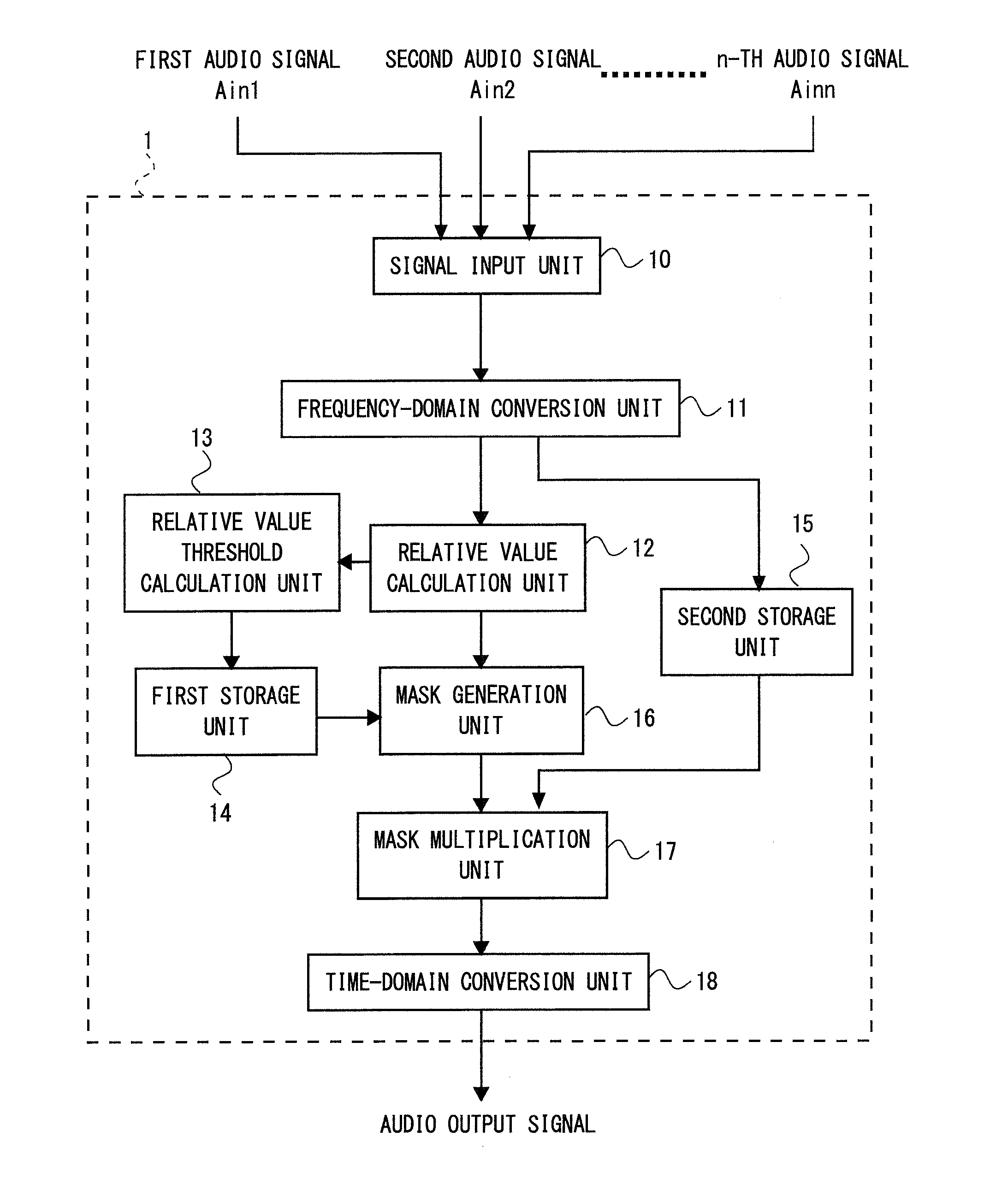
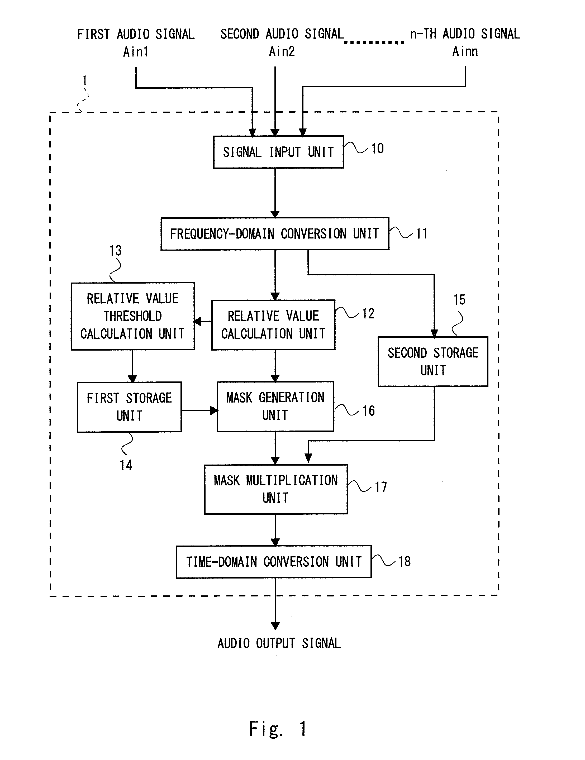
[0027]Hereinafter, with reference to the drawings, embodiments of the present invention will be described. FIG. 1 shows a block diagram of an audio signal processing device 1 according to the first embodiment. The audio signal processing device 1 according to the first embodiment acquires a plurality of audio input signals (first audio input signal Ain1 to n-th audio input signal Ainn shown in FIG. 1) from a plurality of sound acquisition means (e.g., sensors such as microphones) installed at different positions. In the following description, an example of processing of two audio input signals will be described. The audio signal processing device 1 according to the first embodiment emphasizes a predetermined audio signal (hereinafter referred to as a desired audio signal) corresponding to a predetermined time-frequency component included in the audio input signals that are input. The desired audio signal satisfies a condition of a phase difference and an amplitude ratio in a predete...

second embodiment

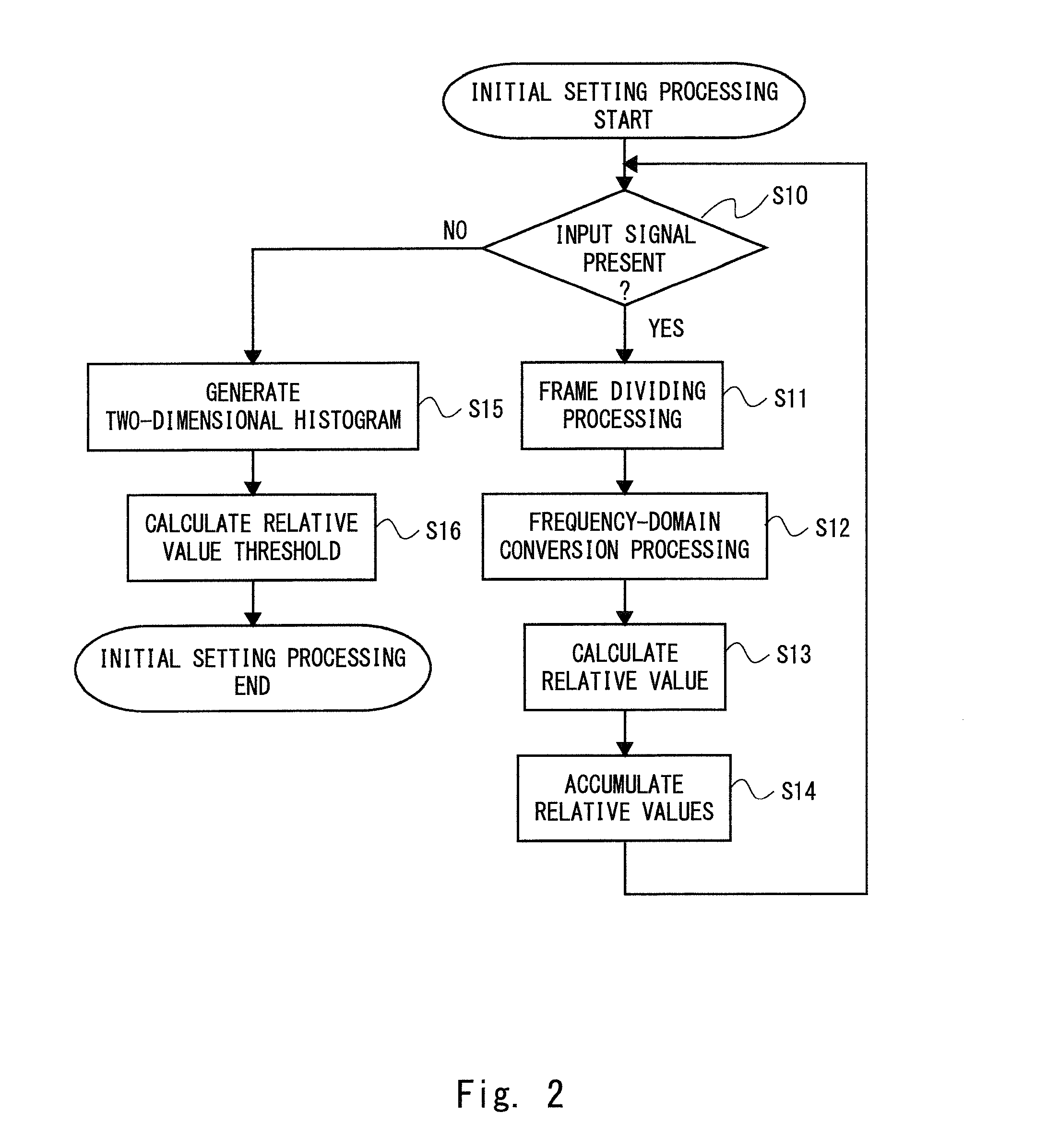
[0065]In the audio signal processing device 1 according to the first embodiment, a so-called non-directional microphone having flat directional characteristics is preferably employed. There is a case, however, in which a microphone having predetermined directional characteristics or a low-cost microphone has to be employed in terms of the system configuration. When the microphone having directional characteristics is employed, a correct relative value may not be calculated in two microphones for signal components coming from a specific direction in terms of the structure. When the low-cost microphone is employed, a correct relative value may not be calculated as well since there may be individual differences in the hardware performance. In such a case, the distribution of the two-dimensional histogram of the phase difference and the amplitude ratio calculated from the plurality of microphones is more complicated than that when the non-directional microphone is used, and it is diffic...


PUM


Abstract

An audio signal processing device includes: a frequency-domain conversion unit that generates a plurality of pieces of frequency-domain information from a plurality of audio input signals acquired at different positions; a relative value calculation unit that calculates, for each piece of frequency-domain information, a relative value between a time-frequency component included in one frequency-domain information and a time-frequency component included in another frequency-domain information; a mask generation unit that compares the relative value with an emphasized range set based on a relative value threshold stored in advance to generate a time-frequency mask that decreases a value of the frequency-domain information corresponding to the relative value which is outside the emphasized range; a mask multiplication unit that multiplies the time-frequency mask by the frequency-domain information to generate emphasized frequency-domain information; and a time-domain conversion unit that converts the emphasized frequency-domain information into an audio output signal indicated as being time-domain information.

Description

INCORPORATION BY REFERENCE[0001]This application is based upon and claims the benefit of priority from Japanese patent application No. 2014-036372, filed on Feb. 27, 2014 and Japanese patent application No. 2014-190137, filed on Sep. 18, 2014, the disclosure of which is incorporated herein in its entirety by reference.BACKGROUND OF THE INVENTION[0002]1. Field of the Invention[0003]The present invention relates to an audio signal processing device, and more specifically, to an audio signal processing device that emphasizes a predetermined audio signal.[0004]2. Description of Related Art[0005]In recent years, techniques for performing various processes on audio signals have been proposed for the purpose of improving the quality of sound transmission or sound recognition rate. Japanese Unexamined Patent Application Publication No. 2006-197552 and Alexander Jourjine, Scott Rickard, Ozgur Yilmaz, “BLIND SEPARATION OF DISJOINT ORTHOGONAL SIGNALS”, ICASSP2000 (Alexander et. Al.) propose on...

Claims


Application Information

Patent Timeline
IPC IPC(8): H04R3/04
CPCH04R3/04G10L21/0232H04B3/20H04B15/00
Inventor SUGANO, MASATO
Owner JVC KENWOOD CORP A CORP OF JAPAN
Why Eureka
Try Eureka