Soldering System Power Supply Unit, Control Unit, Administration Device, and Power Supply-and-Control Device

a technology of power supply and control device, which is applied in the direction of soldering apparatus, instrumentation, computer control, etc., can solve the problems of reduced working area, operator's inability to view the display, and various inconveniences, and achieve the effect of enhancing convenien

Active Publication Date: 2015-09-03
HAKKO CO LTD
View PDF8 Cites 31 Cited by
  • Summary
  • Abstract
  • Description
  • Claims
  • Application Information

AI Technical Summary

Benefits of technology

[0006]The present invention is made in view of the above issues, and the object is to provide a power supply unit, control unit, administration device, and power supply and control device which give enhanced convenience.

Problems solved by technology

Therefore, depending on the usage of the soldering iron equipment, there are various inconveniences.
If not, the operator cannot view the display.
Therefore, there is a problem that the working area is reduced.
Responding to the demand for a higher output power supply specification, the power supply portion must be made larger, resulting in a larger size housing for the soldering iron equipment placed on the work bench, which further decrease the available working area.

Method used


Image

  • Soldering System Power Supply Unit, Control Unit, Administration Device, and Power Supply-and-Control Device
  • Soldering System Power Supply Unit, Control Unit, Administration Device, and Power Supply-and-Control Device
  • Soldering System Power Supply Unit, Control Unit, Administration Device, and Power Supply-and-Control Device

Examples


Embodiment Construction

[0031]The following describes the best known system to achieve the invention with reference to the accompanying drawings. Those skilled in the art may appreciate alternative configurations for the concept following review of this specification. Accordingly, the description herein is intended to be exemplary, but not limiting with respect to the proper scope of the appended claims.

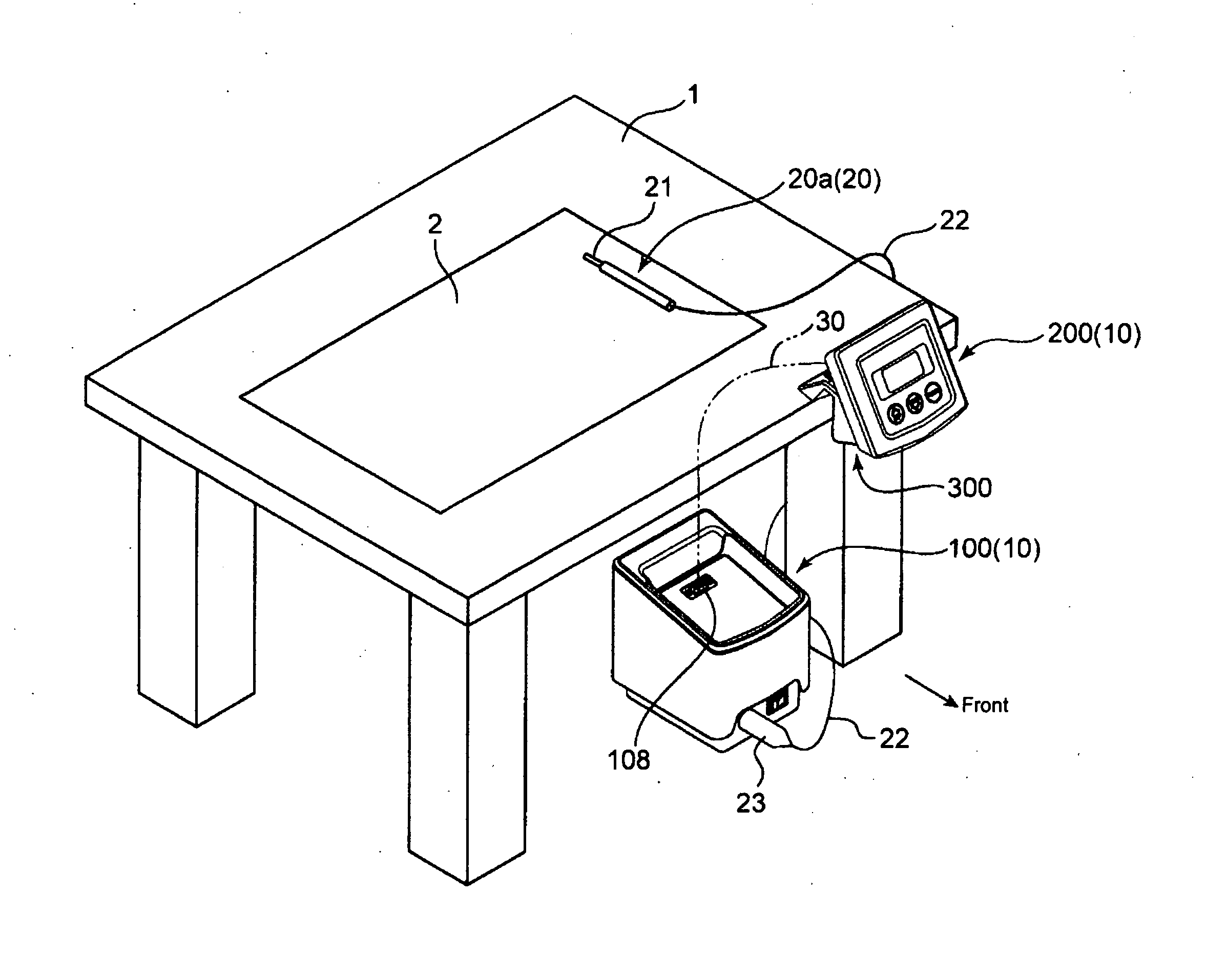
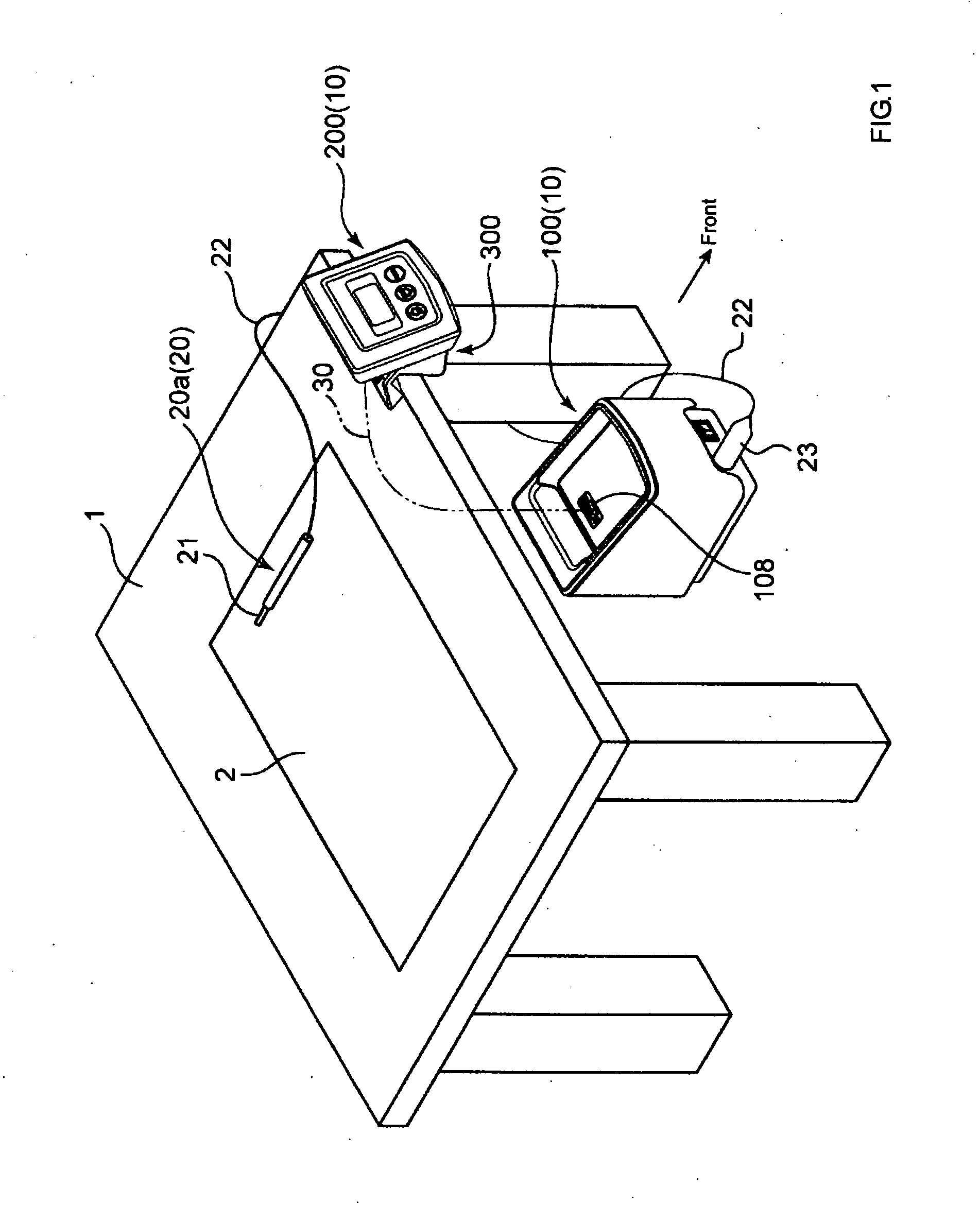
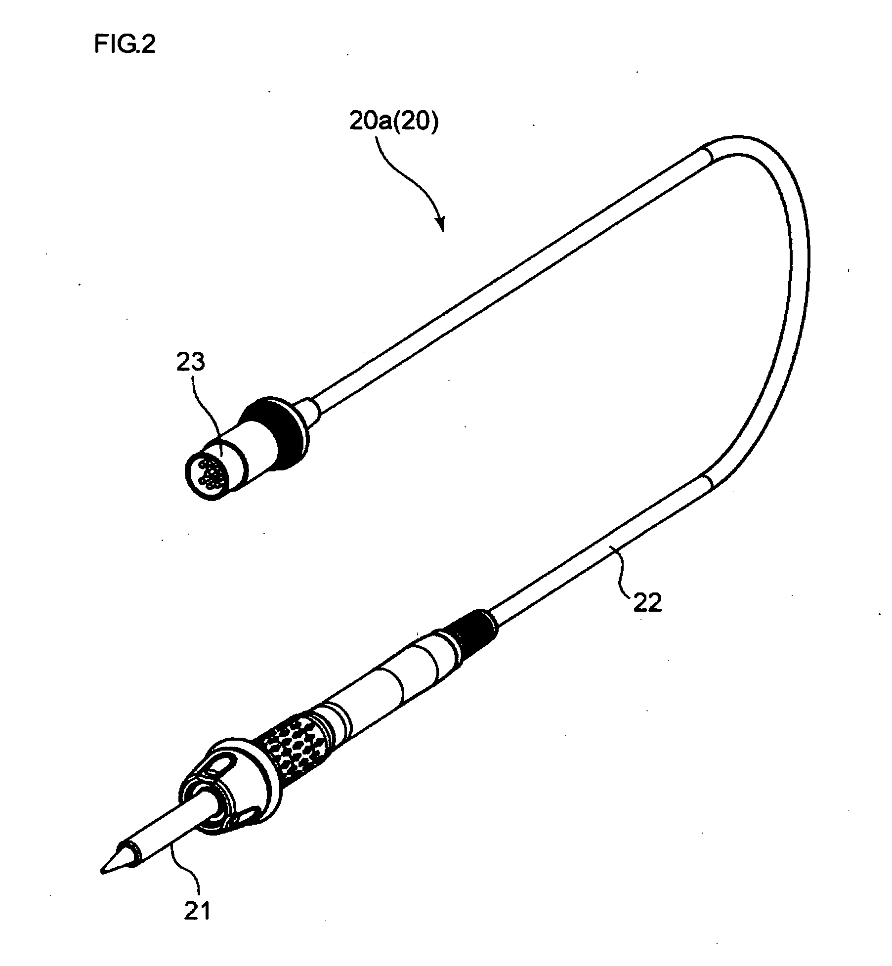
[0032]Referring to FIG. 1, illustratively shown but not limited thereto, soldering system 10 comprises a power supply unit 100 and a control unit 200 that are configured to control a plurality of types of soldering devices 20. Power supply unit 100 and control unit 200 are to be used at a work bench 1 where the solder handling operation is being worked. On the work bench 1, a working mat 2 may be provided. An operator will work or perform soldering or desoldering operations on the working mat 2. At the side of the working mat 2, the soldering device 20 may be placed in a holder (not shown). As illustrated i...


PUM

PropertyMeasurementUnit
voltageaaaaaaaaaa
voltageaaaaaaaaaa
voltageaaaaaaaaaa

Abstract

The present invention is intended to ease the control and management of soldering devices, and enhance convenience. In accordance with the intention of the invention, a system includes a power supply unit having a connecting cable to be connected to soldering devices, a power supply portion supplying power to the soldering devices through the connecting cable, a power supply control portion to control the power supply from the power supply portion based on a temperature setting signal T(s) set in advance and a control unit that may be physically separated from the power supply unit but which inputs the temperature setting signal T(s) to the power supply control portion of the power supply unit.

Description

FIELD OF THE INVENTION[0001]The present invention relates to a soldering system including a power supply unit, control unit, administration device, and power supply and control device.[0002]In the electronics industry, even today, the task of soldering electronic components is often a manual operation. The soldering function is performed by setting the work area on a work bench. The worker will operate the soldering device facing the work area. The soldering devices may include soldering irons, desoldering irons, and tweezers but they are not limited thereto. The individual soldering device is connected to a power supply and control device. The power supply and control device controls the heat generation of the soldering device mainly by adjusting the voltage applied to the soldering device. Conventional power supply and control devices include a power supply portion supplying power to the soldering device, a power supply control portion controlling the voltage output from the power...

Claims


Application Information

Patent Timeline
Patent Type & Authority Applications(United States)
IPC IPC(8): B23K1/00G05B15/02
CPCG05B15/02B23K1/0004B23K3/00B23K3/03B23K3/08
Inventor TERAOKA, YOSHITOMONAKAMURA, KENTAIGI, YASUMASA
Owner HAKKO CO LTD
Why Eureka
Try Eureka