
Multilevel Power Conversion Circuit and Device

a power conversion circuit and multi-level technology, applied in power conversion systems, ac-dc conversion without reversal, electrical equipment, etc., can solve the problems of limiting the degree to which efficiency can be improved, high switching loss, and large electromagnetic noise generated upon switching, so as to reduce loss, noise, production cost, and device size , the effect of improving reliability

Inactive Publication Date: 2015-09-03
NAT INST OF ADVANCED IND SCI & TECH
View PDF9 Cites 25 Cited by
  • Summary
  • Abstract
  • Description
  • Claims
  • Application Information

AI Technical Summary

Benefits of technology

The present invention provides a flying capacitor circuit-type multilevel power conversion circuit that can adjust the voltages of flying capacitors to prescribed values without detecting voltage values. This makes it faster than conventional art. A multilevel power conversion device using this circuit can be reduced in loss, noise, production cost, and device size, and improved in reliability. The main semiconductor switches can be one-chip-integrated, preventing element destruction, leading to improved reliability. The function of adjusting the voltages of flying capacitors can be obtained regardless of the destination to which the output terminal of the load is connected, enhancing versatility and reducing production cost. The resistor can be disposed close to the main semiconductor switches, suppressing a parasitic inductance that leads to higher speed adjustment of flying capacitors. The invention mitigates the trade-off between electricity consumed by the resistor and its ability to adjust the voltages of flying capacitors, reducing electricity consumption.

Problems solved by technology

A first problem is that an output voltage includes a lot of harmonics, which gives rise to a need for a large harmonic filter for outputting a favorable alternating or direct current including a low amount of harmonic components.
A second problem is that a lot of electromagnetic noise is generated upon switching.
A third problem is that a switching loss is high, which limits the degree to which the efficiency can be improved.
Furthermore, they can suppress electromagnetic noise and switching loss, because a voltage to be applied per switching element of a main circuit is low.
Meanwhile, multilevel power conversion circuits have a problem in terms of capacitor voltage control.
If the voltages of the capacitors depart from the specific values, various problems occur such as distortion of the output waveform, growth of electromagnetic noise, destruction of a main semiconductor switch of a main circuit, and destruction of the capacitors themselves.
The problem of element or capacitor destruction is particularly critical in one-chip integrated circuits.
Because it is impossible to replace the elements on the one-chip integrated circuits individually, it is necessary to replace the entire integrated circuit when one element is destroyed.
However, power conversion circuits actually used have variations in the characteristics of the main semiconductor switches, and include parasitic elements in the circuit such as a parasitic resistance, a parasitic capacity, and a parasitic inductance.
However, with this method, numerous voltage sensors must be prepared in conjunction with increase in the number of levels, which is infeasible in terms of the volume and cost of the conversion device.
Further, as the number of levels is increased, the number of operation modes of the circuit increases exponentially, and it is practically impossible for one operation mode to be selected from among these operation modes based on the voltages of the respective flying capacitors.

Method used


Image

  • Multilevel Power Conversion Circuit and Device
  • Multilevel Power Conversion Circuit and Device
  • Multilevel Power Conversion Circuit and Device

Examples


example 1

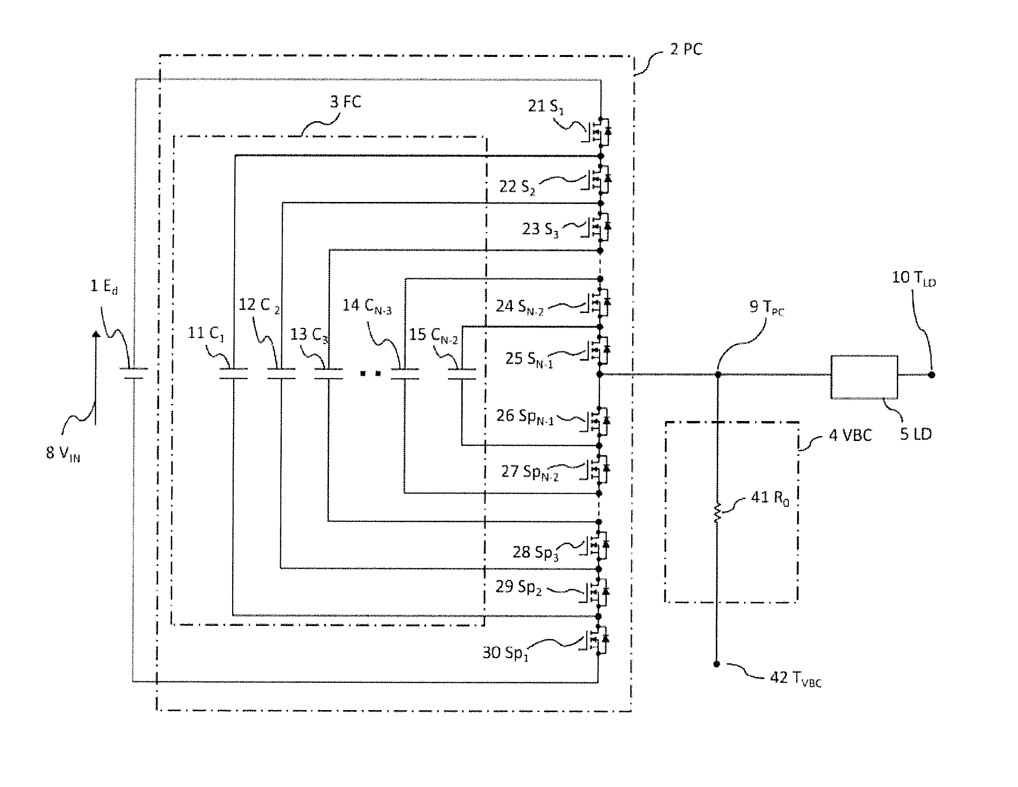
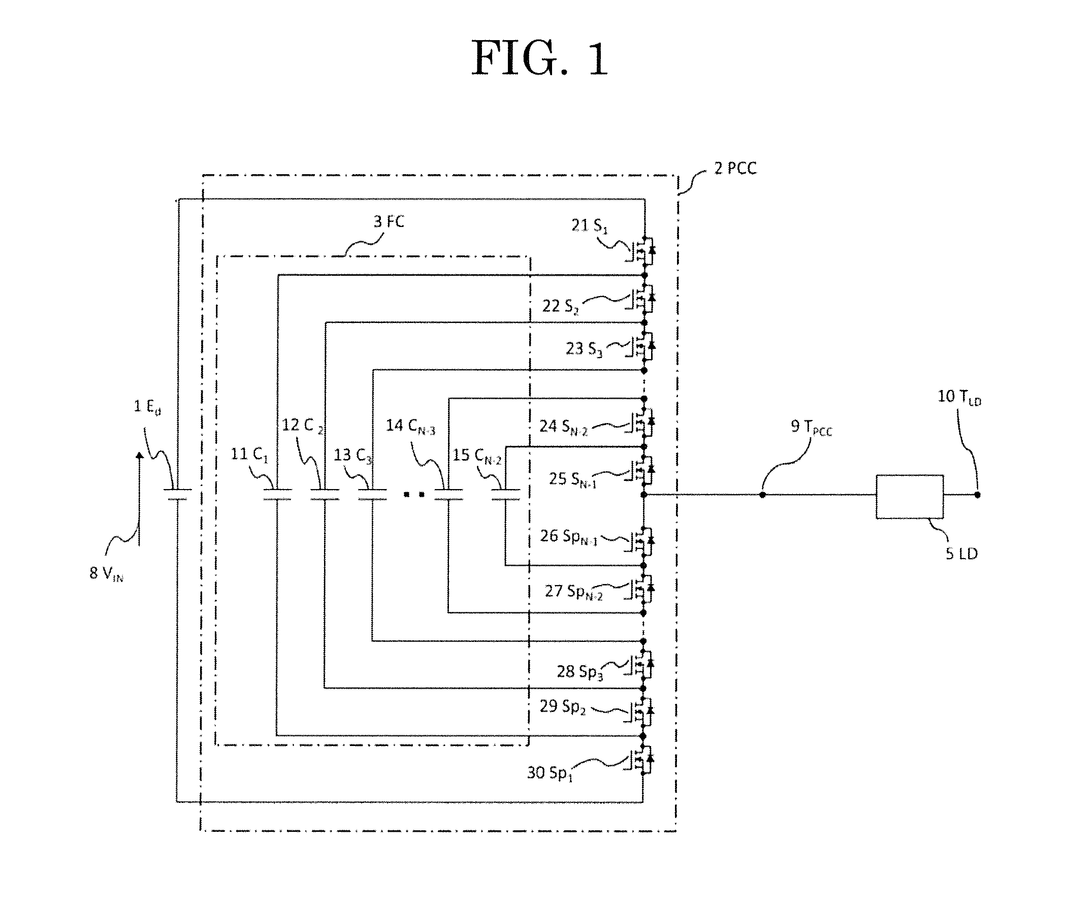
[0153]The effect of the present invention in the circuit configuration of FIG. 6 was verified based on a virtual experiment by simulation. A circuit used was a flying capacitor circuit-type multilevel power conversion circuit in a five-level DC-AC power conversion device. A circuit configuration of FIG. 1 was used as a circuit configuration of a conventional art. A circuit configuration of FIG. 6 was used as a circuit configuration of the present invention. Because the device was five-level, N was 5, three flying capacitors were involved, namely C1, C2, and C3, and eight main semiconductor switches were involved, namely S1, S2, S3, S4, SP1, SP2, Sp3, and Sp4.

[0154]As calculation conditions, an input voltage was 200 V, the capacitance of the flying capacitors was 10 μF, a load was a serial circuit of a resistor having a resistance value of 30Ω and an inductor having an inductance of 80 mH, the frequency of the fundamental wave of an output was 50 Hz, a carrier frequency was 2 kHz (a ...

example 2

[0159]The effect of the present invention in the circuit configuration of FIG. 17 was verified based on a virtual experiment by simulation. A circuit used was a flying capacitor circuit-type multilevel power conversion circuit in a five-level DC-AC power conversion device. A circuit configuration of FIG. 1 was used as a circuit configuration of a conventional art. A circuit configuration of FIG. 17 was used as a circuit configuration of the present invention. Because the device was five-level, N was 5, three flying capacitors were involved, namely C1, C2, and C3, and eight main semiconductor switches were involved, namely S1, S2, S3, S4, Sp1, Sp2, Sp3, and Sp4.

[0160]As calculation conditions, an input voltage was 200 V, the capacitance of the flying capacitors was 10 μF, a load was a serial circuit of a resistor having a resistance value of 30Ω and an inductor having an inductance of 80 mH, the frequency of the fundamental wave of an output was 50 Hz, a carrier frequency was 2 kHz (...

example 3

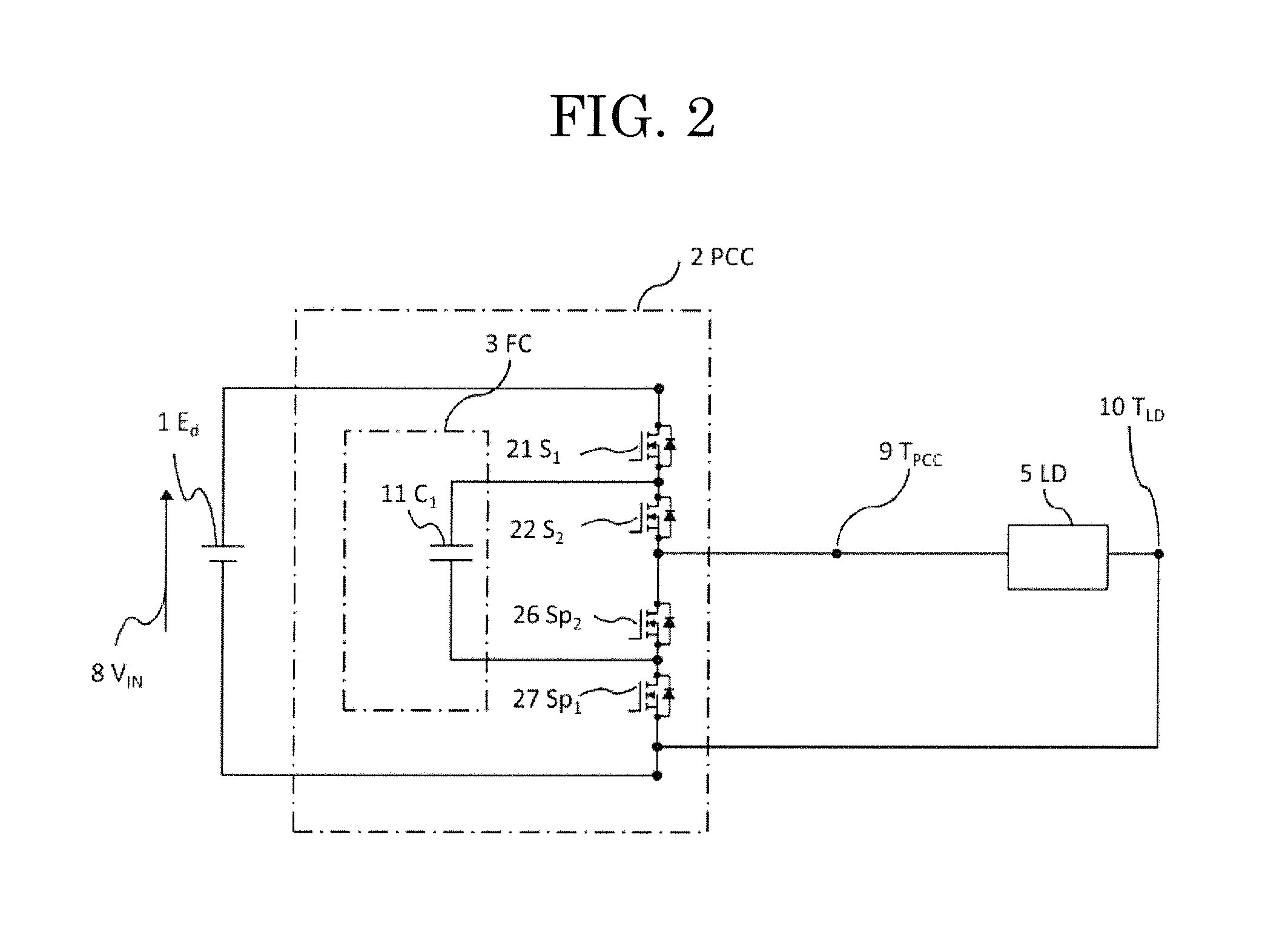
[0165]A prototype of a DC-AC power conversion device was produced, and the effect of the present invention with this device was verified by an experiment. A circuit used was a three-level flying capacitor circuit-type multilevel power conversion circuit. A circuit configuration of FIG. 1 was used as a circuit configuration of a conventional art. A circuit configuration of FIG. 17 was used as a circuit configuration of the present invention. Because the device was three-level, N was 3, only one flying capacitor was involved, namely C1, and four main semiconductor switches were involved, namely S1, S2, Sp1, and Sp2.

[0166]As calculation conditions, an input voltage was 100 V, the capacitance of the flying capacitor was 8.2 μF, a load was a serial circuit of a resistor having a resistance value of 10Ω and an inductor having an inductance of 40 mH, the frequency of the fundamental wave of an output was 50 Hz, and a carrier frequency was 2 kHz. All of the main semiconductor switches were ...


PUM


Abstract

[Solution] An actually used flying capacitor-type multilevel power conversion circuit has variations in the characteristics of main semiconductor switches, and includes parasitic elements such as parasitic resistance, parasitic capacity, and parasitic inductance in the circuit, which causes flying capacitors to be charged and discharged to different quantities contrary to ideal case, making it necessary to have voltage sensors for flying capacitor voltage detection and a main semiconductor switch control mechanism in order to suppress fluctuation of the flying capacitor voltages from prescribed values. Furthermore, this circuit becomes unpractical when the number of levels is increased. The present invention provides a circuit that adjusts flying capacitor voltages to prescribed values automatically without voltage sensors for detection of individual flying capacitor voltages, and a main semiconductor switch control mechanism, by additionally providing a main circuit thereof with a closed circuit for suppressing flying capacitor voltage fluctuations by means of an adjusting current.

Description

TECHNICAL FIELD[0001]The present invention relates to a multilevel power conversion circuit, and particularly to a circuit technique and device for adjusting voltage of a flying capacitor in a flying capacitor circuit-type multilevel power conversion circuit.BACKGROUND ART[0002]Generally, power conversion circuits in power conversion devices are two-level power conversion circuits capable of outputting a binary (two-valued) voltage.[0003]Two-level power conversion circuits have the following three problems. A first problem is that an output voltage includes a lot of harmonics, which gives rise to a need for a large harmonic filter for outputting a favorable alternating or direct current including a low amount of harmonic components. A second problem is that a lot of electromagnetic noise is generated upon switching. A third problem is that a switching loss is high, which limits the degree to which the efficiency can be improved.[0004]To solve the above-described problems of the two-...

Claims


Application Information

Patent Timeline
Patent Type & Authority Applications(United States)
IPC IPC(8): H02M7/537H02M7/25
CPCH02M7/25H02M7/537H02M1/32H02M7/483H02M7/4837
Inventor SATO, YUKIHIKOOBARA, HIDEMINEOHASHI, HIROMICHINAKAJIMA, AKIRANISHIZAWA, SHINICHI
Owner NAT INST OF ADVANCED IND SCI & TECH
Learn More