End mill

Active Publication Date: 2015-09-10
GUEHRING OHG
View PDF15 Cites 4 Cited by
  • Summary
  • Abstract
  • Description
  • Claims
  • Application Information

AI Technical Summary

Benefits of technology

[0018]The further developments in claims 13 and 14 improve the cutting behavior of the end mill at locations where the cutting speed is

Problems solved by technology

It has been found that the known geometries of the generic face mills are often inadequate for maintaining the required

Method used


Image

  • End mill
  • End mill
  • End mill

Examples


Example

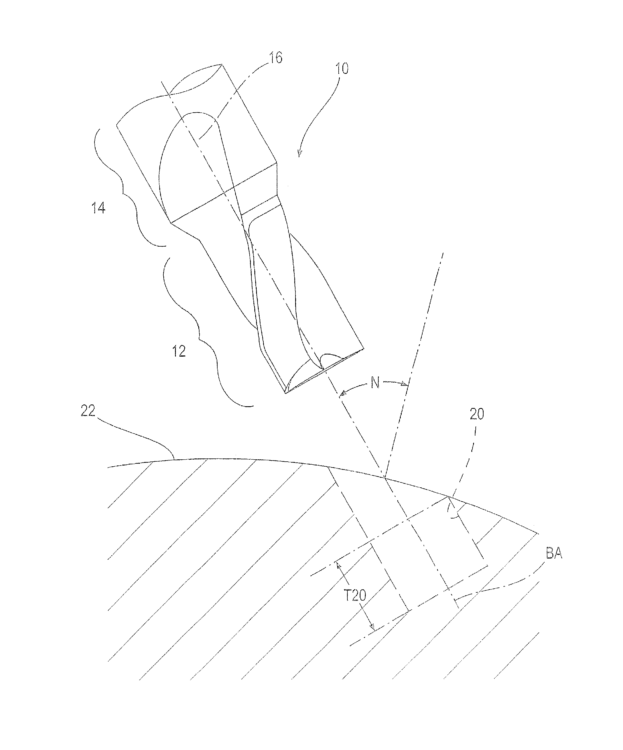
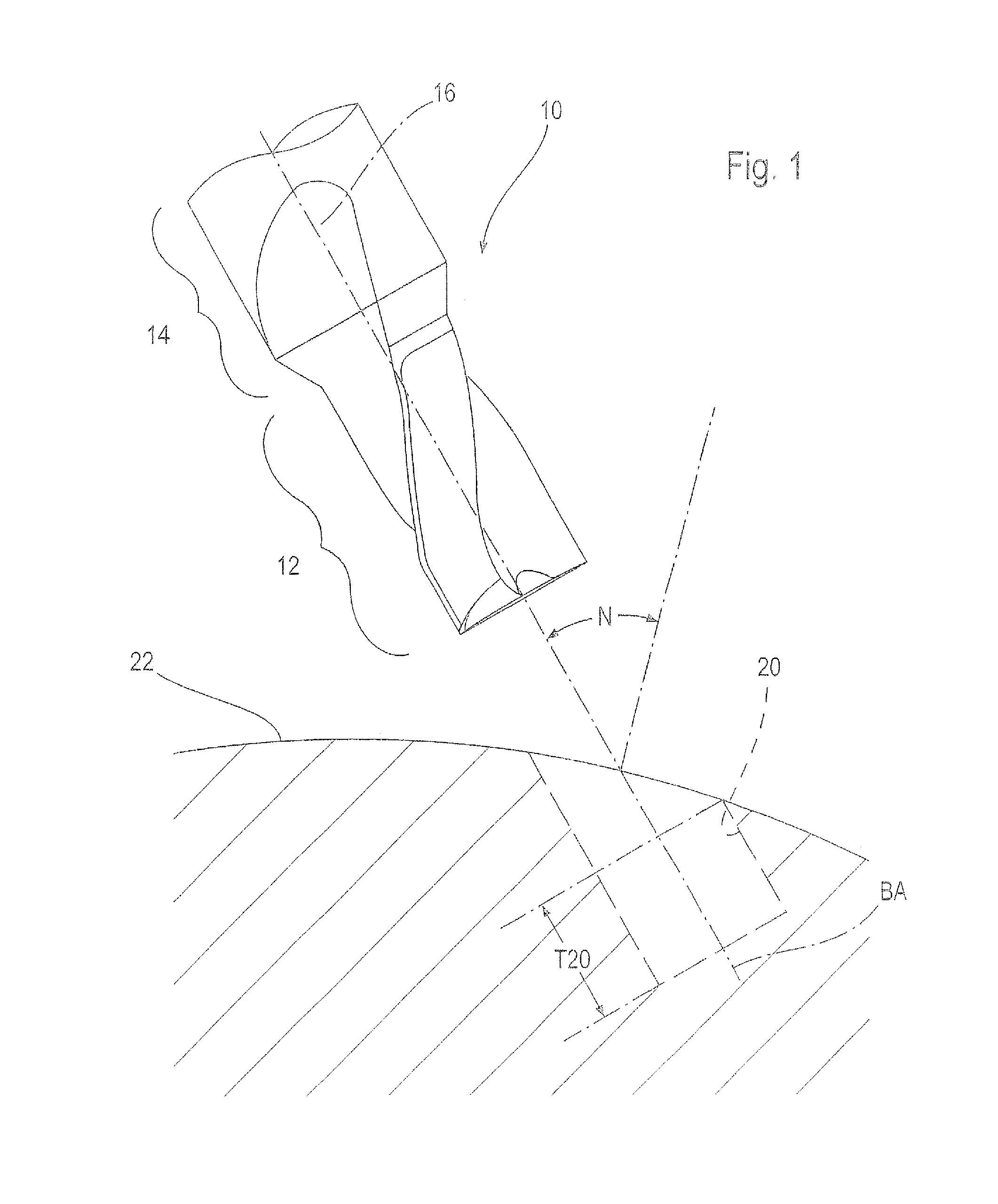
[0027]Labeled with reference number 10 on FIG. 1 is an end mill, which apart from conventional milling operations is also to be used for expanding holes, and also to pilot and chamfer in particular inclined work piece surfaces.

[0028]The dashed lines on FIG. 1 denote such a pilot hole 20, which is inclined at an inclination angle N relative to the work piece surface 22. The higher the inclination angle N, the more difficult it becomes to maintain a pilot hole having a sufficiently high accuracy with respect to the alignment of the hole axis and in terms of roundness in particular over the entire, fully formed hole depth T20. The dimensional accuracy of the pilot hole 20 is thus often required, since the pilot hole is used as a guide for the drill tool to be subsequently used in order to fabricate deeper holes. For example, this is why it has in the meantime become necessary at a hole diameter of 10 mm to keep the roundness deviations within a range of 3 to 6 μm over the entire length...


PUM

PropertyMeasurementUnit
Angleaaaaaaaaaa
Angleaaaaaaaaaa
Angleaaaaaaaaaa

Abstract

Described is an end mill with four straight front cutting edges arranged on a front side and a corresponding number of circumferential cutting edges that each emanate from the outer nose of the front cutting edges and are separated from each other by flutes. One of the front cutting edges passes over into a second cutting edge via a free surface intersecting line. The additional front cutting edges lying between the latter in the cutting direction are offset relative to each other by a first angular pitch of 180°, and end before the middle. So that the end mill can be used in an especially advantageous manner for incorporating dimensionally and positionally precise pilot holes or chamfering curved work piece surfaces, the first front cutting edge is offset relative to the second front cutting edge in the cutting direction by a second angular pitch ranging between 173° and 177°, preferably between 174° and 176°, wherein the first front cutting edge is offset relative to the next additional front cutting edge in the cutting direction by a third angular pitch ranging between 90° and 94°, preferably between 91° and 93°.

Description

BACKGROUND OF THE INVENTION[0001]1. Field of the Invention[0002]The invention relates to an end mill.[0003]2. Description of Related Art[0004]Such end mills are basically known, for example from DE 103 25 600 B4 or the “Pilot Mill” journal of the applicant from 2013.[0005]Milling tools of this kind have more recently been used when holes, including deep holes, have to be introduced at an inclination to a work piece surface. In this case, the face mill is used to “chamfer” the work piece surface or provide it with a pilot hole, which during the ensuing hole machining process serves as a guide for the drill, for example a gun drill.[0006]The incremental improvements made to the materials for the used tools have also been accompanied by a rising quality of such pilot holes and chamfered surfaces. Improving the stiffness of the tools, for example by using hard materials like solid carbide (VHM), makes the dimensional accuracy of the pilot holes very good even if they are introduced into...

Claims


Application Information

Patent Timeline
IPC IPC(8): B23C5/10
CPCB23C5/10B23C2220/04B23C2210/203B23C2210/282B23C2250/16Y10T409/303752Y10T407/1948B23C5/1081B23C2210/00
Inventor MUTLU, MURATWEIMANN, STEFANGALL, CLEMENS
Owner GUEHRING OHG
Why Eureka
Try Eureka