
Distance, diameter and area determining device

a technology of distance, diameter and area, applied in the field of methods and medical devices, can solve the problems of stent underexpansion, stent failure, and inability of physicians to adequately assess the lesion, and achieve the effect of simplifying the way of calculating cross-sectional dimensions

Active Publication Date: 2015-09-17
PROVISIO MEDICAL INC
View PDF3 Cites 43 Cited by
  • Summary
  • Abstract
  • Description
  • Claims
  • Application Information

AI Technical Summary

Benefits of technology

The invention describes a way to use ultrasound or OCT technology to approximate the dimensions of structures, such as fluid-filled organs or other structures. The invention includes an elongated member, like a catheter, that has multiple ultrasound transducers embedded in it. These measurements are used to approximate the shape and size of the structure into which the catheter is placed. The invention also includes a method for creating three-dimensional images from two-dimensional images. Overall, the invention simplifies the process of calculating cross-sectional dimensions and creating three-dimensional maps compared to previous devices and techniques.

Problems solved by technology

Recent imaging studies have illustrated that the predominate cause of residual stent failure is stent underexpansion and lesion edge problems such as undersizing the length of the stent needed to appropriately cover the lesion.
The limitations of today's angiogram often do not allow the physician to adequately assess the lesion prior to stent placement or determine the degree of expansion of the deployed stent.
This is a problem in need of a solution.
But, although current IVUS and OCT systems provide additional and more detailed information compared to angiograms, these IVUS and OCT systems introduce significant additional time, cost and complexity into minimally-invasive procedures.
Further, the images produces by IVUS and OCT systems often are subject to interpretation of the physician.

Method used


Image

  • Distance, diameter and area determining device
  • Distance, diameter and area determining device
  • Distance, diameter and area determining device

Examples


Embodiment Construction

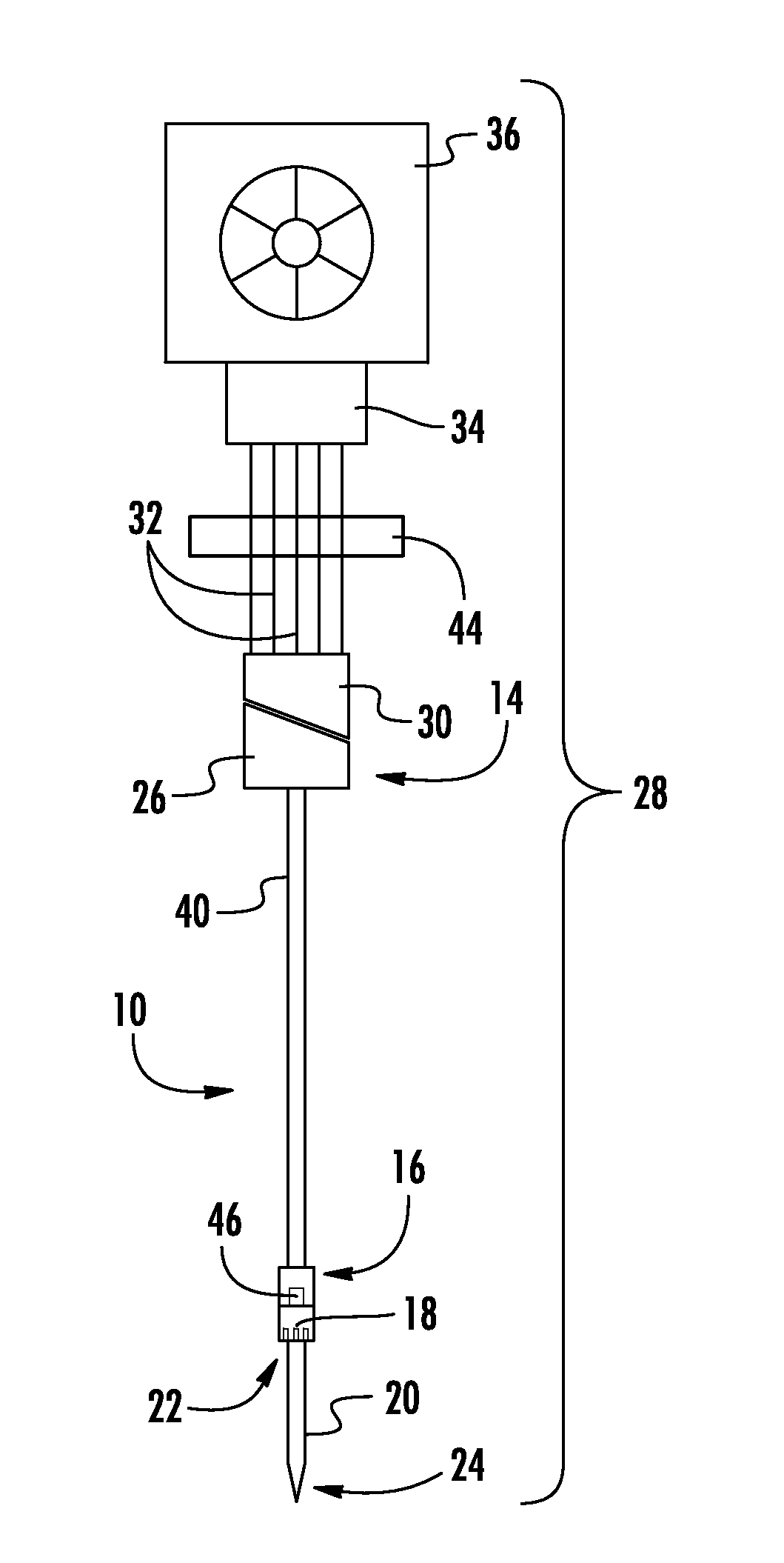
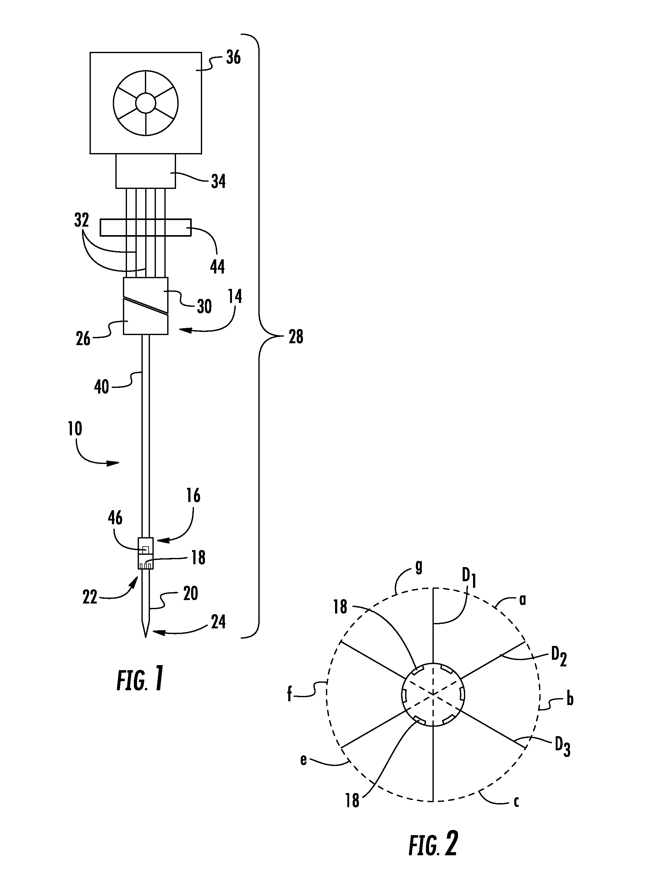
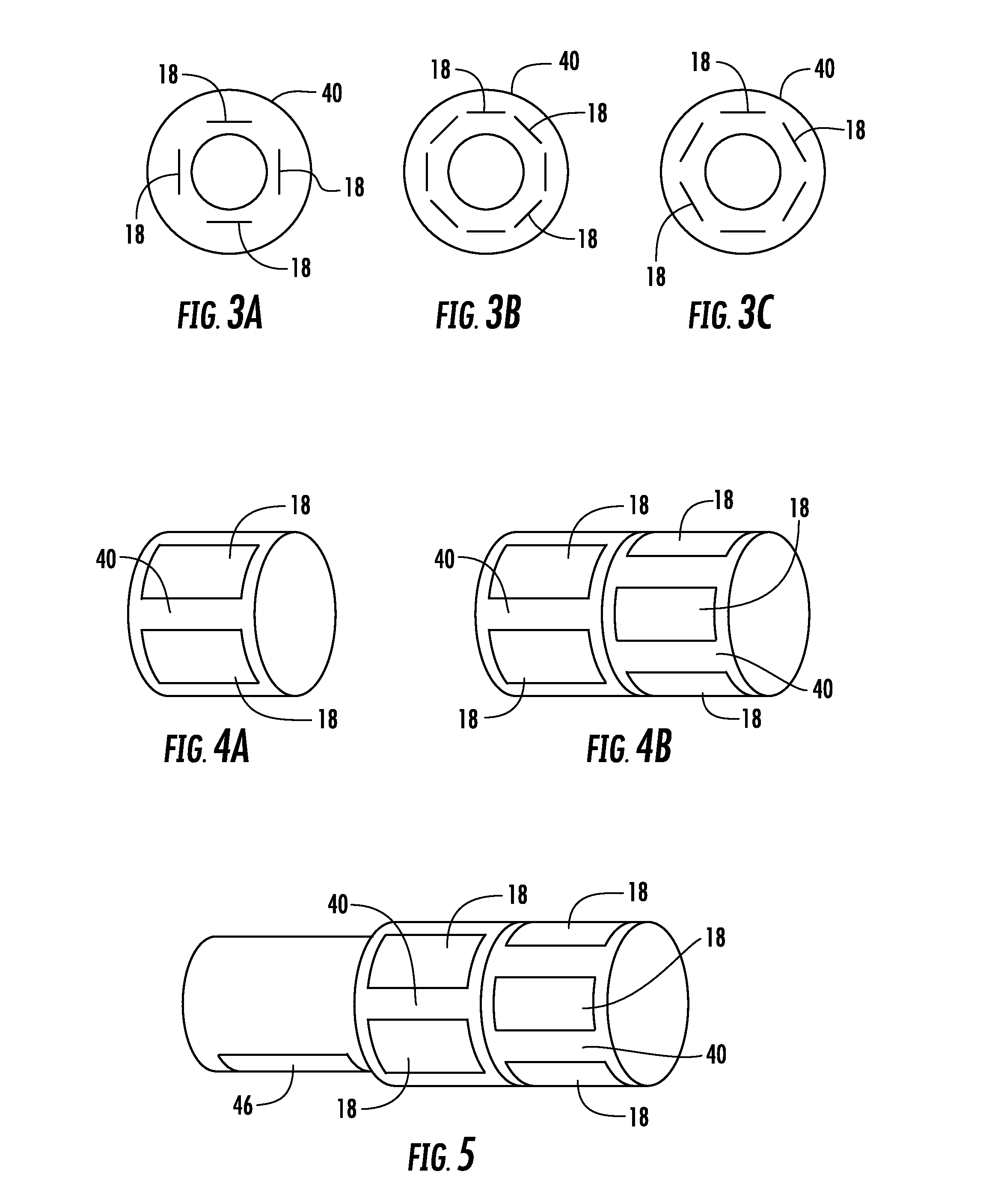
[0024]In order that the invention may be clearly understood and readily carried into effect, preferred embodiments of the invention will now be described with reference to the accompanying drawings. The description of these embodiments is given by way of example only and not to limit the invention. The medical device of the present invention, in all of its embodiments, is shown in the drawings generally labeled 10. A preferred embodiment of the present invention being described herein is a catheter. But, the invention applies to many other devices where knowing the dimensions around the medical device 10 is desirable.

[0025]As mentioned above, although a preferred embodiment of the present invention is a catheter, the invention applies to many other devices where it is desirable to know the cross-sectional dimensions the space surrounding the medical device 10. Examples of such medical devices 10 include, but are not limited to, conventional intravascular ultrasound (IVUS), optical c...


PUM


Abstract

The invention describes a novel implementation of ultrasound or OCT technology to approximate the dimensions of fluid-filled structures (when using ultrasound technology) or other structures (when using OCT technology). The invention in a preferred embodiment is an elongated member such as a catheter that uses ultrasound or OCT technology to approximate the dimensions of a structure into which the catheter has been placed. In a preferred embodiment, the catheter includes multiple ultrasound transducers arranged in an annular or circumferential configuration on, embedded into or within the body of the elongated member so that distance measurements can be obtained between the elongated member and the wall of the immediately facing structure (e.g., a fluid-filled lumen). Utilizing these measurements, the present invention approximates for the physician the shape and size of the structure into which the elongated member is placed. The invention also includes a method for producing three-dimensional images from two-dimensional images.

Description

BACKGROUND OF THE INVENTION[0001]1. Field of the Invention[0002]The present invention relates generally to methods and medical devices that gather information about vessels, structures or devices in a body and more particularly to methods and medical devices for measuring dimensions of such vessels, structures or devices and calculate cross-sectional areas of such vessels, structures or devices.[0003]2. Description of Related Art[0004]Within the field of interventional cardiology, the utilization of coronary drug-eluting stents has significantly reduced stent failure and the need for revascularization. Recent imaging studies have illustrated that the predominate cause of residual stent failure is stent underexpansion and lesion edge problems such as undersizing the length of the stent needed to appropriately cover the lesion. The limitations of today's angiogram often do not allow the physician to adequately assess the lesion prior to stent placement or determine the degree of expan...

Claims


Application Information

Patent Timeline
IPC IPC(8): A61B8/00A61B5/107A61B8/08A61B8/12A61B5/00
CPCA61B8/445A61B8/12A61B5/0095A61B8/4494A61B5/1076A61B8/5223A61B8/5238A61B8/08A61B5/1079A61B8/54A61B5/0066A61B5/0084A61B5/6852A61B8/0891A61B8/483A61B8/5261A61F2/958G16H50/30A61B5/0035A61B5/055A61B6/032A61B6/487A61B8/4488A61B8/463
Inventor RYAN, STEPHEN ERIC
Owner PROVISIO MEDICAL INC
Learn More