Firmware Design for Area and Location Data Management of Biological Air Samples Collected on Media Plates

a technology for biological air samples and firmware, applied in the field of particle sampling, collection and analysis, can solve problems such as particularly difficult managemen

Inactive Publication Date: 2015-09-17
PARTICLE MEASURING SYST
View PDF2 Cites 27 Cited by
  • Summary
  • Abstract
  • Description
  • Claims
  • Application Information

AI Technical Summary

Benefits of technology

[0010]Provided herein are methods and devices for achieving simple and straightforward management of many different sampling locations within a facility. This management can be particularly challenging for applications where there may hundreds or more of unique sampling locations, and each sampling location having a sample associated therewith.

Problems solved by technology

This management can be particularly challenging for applications where there may hundreds or more of unique sampling locations, and each sampling location having a sample associated therewith.

Method used


Image

  • Firmware Design for Area and Location Data Management of Biological Air Samples Collected on Media Plates
  • Firmware Design for Area and Location Data Management of Biological Air Samples Collected on Media Plates
  • Firmware Design for Area and Location Data Management of Biological Air Samples Collected on Media Plates

Examples


example 1

Impactors

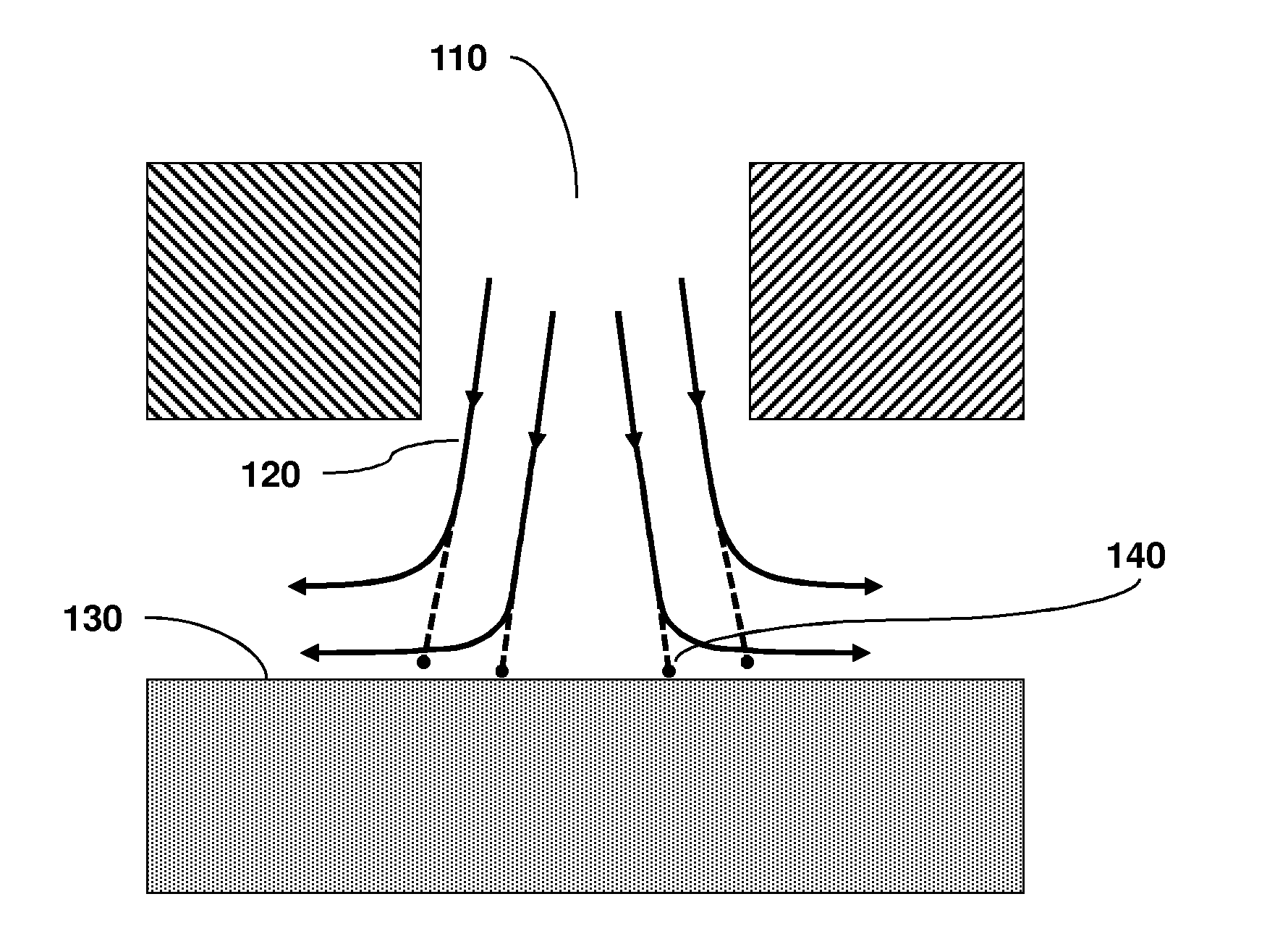
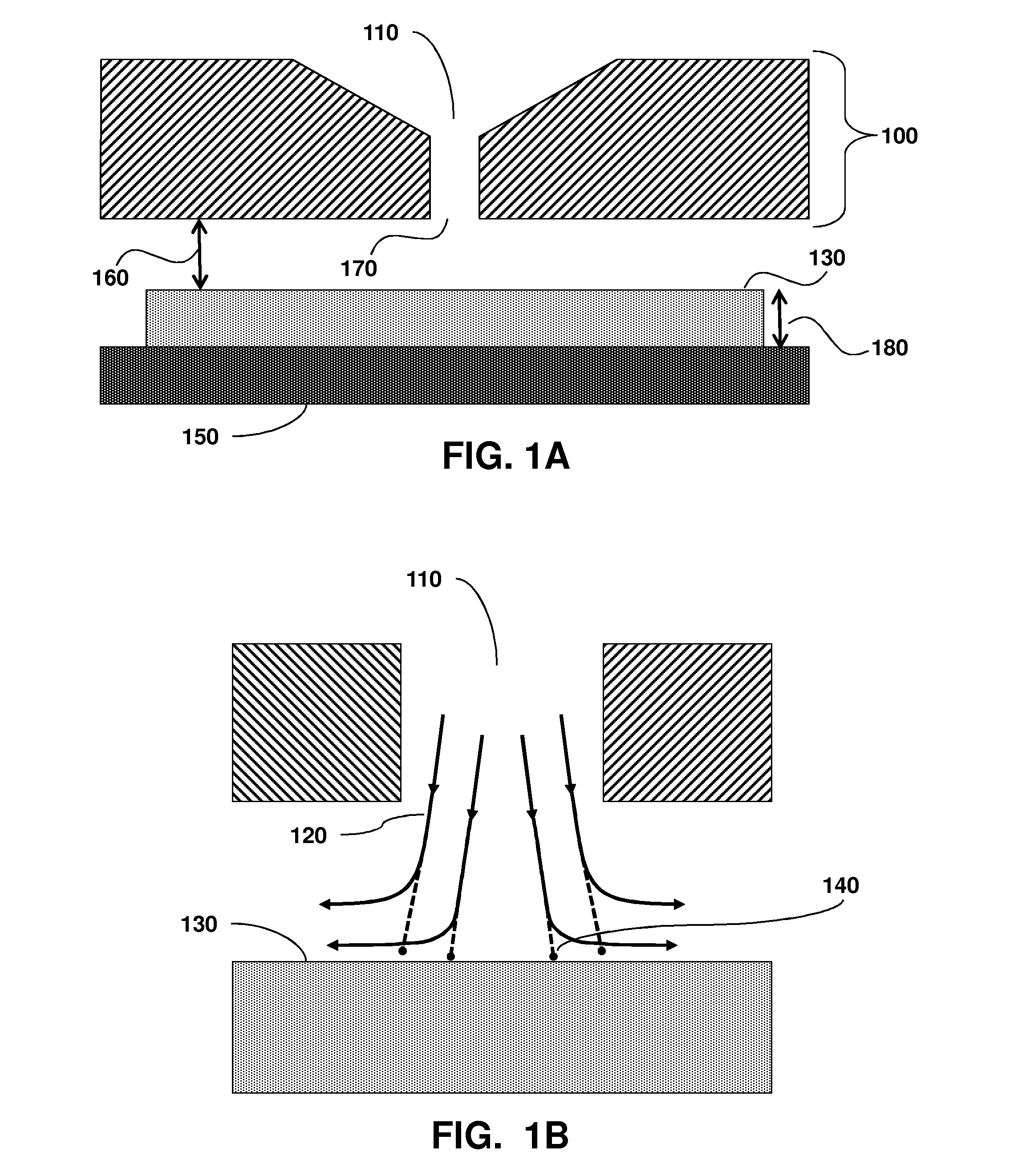
[0050]FIG. 1A provides a schematic diagram illustrating the general construction of a particle impactor and FIG. 1B illustrates an expanded view of a particle impactor to further illustrate the operational principal. As shown in these Figures, gas flow is directed through an intake aperture 110 in a sampling head 100 where it is accelerated towards an impact surface 130, which forces the gas to rapidly change direction, following flow paths or streamlines 120 under laminar fluid flow conditions. Due to their momentum, particles 140 entrained in the gas flow are unable to make the rapid change in direction and impact on the impact surface 130. In the embodiment shown in FIG. 1A and FIG. 1B, impact surface 130 is supported by impactor base 150. In embodiments, impact surface 130 comprises the receiving surface of a growth medium, such as agar, provided in a growth medium container or petri dish. Viable biological particles collected on the impact surface, for example, can sub...

example 2

Firmware Design for Area and Location Data Management of Biological Air Samples Collected on Media Plates

[0052]The firmware is structured to allow for simple management of many different sampling locations within a facility.

[0053]When samples need to be taken at many locations within a facility the current practice is to either enter a specific location onto a sampler manually every time a sample is taken or to manually track the sample either through the use of external paperwork (or electronic methods), or directly onto the sampling plate.

[0054]By creating firmware that structures the samples to be taken into a hierarchal fashion it is possible to identify a specific AREA within a facility for example, Filing Line 1. As well as a specific LOCATION within that area, such as Background Location 1.

[0055]With this type of structure it simplifies the user's selection of the sample point within a particular area and the specific location within that area. This two tiered structure reduc...


PUM

PropertyMeasurementUnit
sizeaaaaaaaaaa
sizeaaaaaaaaaa
sizeaaaaaaaaaa

Abstract

Provided herein are methods and devices that allow for efficient management of many different sampling locations within a facility. A method for operating a biological sampler is described, such as by sampling an environment at a sampling position with the biological sampler and associating the sampling position with a unique identifier, wherein the unique identifier comprises an area and a location. Also provided are associated devices for carrying out the methods.

Description

CROSS-REFERENCE TO RELATED APPLICATIONS[0001]This application claims the benefit of priority from U.S. Provisional Patent Application No. 61 / 953,315 filed Mar. 14, 2014, which is hereby incorporated by reference in its entirety to the extent not inconsistent herewith.BACKGROUND OF INVENTION[0002]The invention is generally in the field of particle sampling, collection and analysis. The invention relates generally to devices and methods for sampling and characterizing particles in fluids include air and process chemicals (e.g., gases and liquids) for applications including the evaluation of contaminants in a range of cleanroom and manufacturing environments. More specifically, provided are methods and systems that provide for management of many different sampling locations within a facility.[0003]Cleanrooms and clean zones are commonly used in semiconductor and pharmaceutical manufacturing facilities. For the semiconductor industry, an increase in airborne particulate concentration ca...

Claims


Application Information

Patent Timeline
Patent Type & Authority Applications(United States)
IPC IPC(8): C12Q1/24G01N1/22C12Q1/70
CPCC12Q1/24G01N1/2226C12Q1/70G01N1/26G01N2001/282
Inventor HARTIGAN, PAUL B.KETCHAM, CLIFF
Owner PARTICLE MEASURING SYST
Why Eureka
Try Eureka