
Flattened Dihedral-Shaped Device Possessing an Adapted (Maximized Or Minimized) Equivalent Radar Cross Section

a dihedral-shaped, dihedral-shaped technology, applied in the direction of antennas, electrical equipment, etc., can solve the problems of parasitic radiation and complexity in design, more difficult structure implementation, and destructive summation of waves reflected by each of these materials, so as to achieve the effect of maximizing the rcs

Inactive Publication Date: 2015-09-17
INSTITUT NAT DES SCI APPLIQUEES INSA +1
View PDF10 Cites 4 Cited by
  • Summary
  • Abstract
  • Description
  • Claims
  • Application Information

AI Technical Summary

Benefits of technology

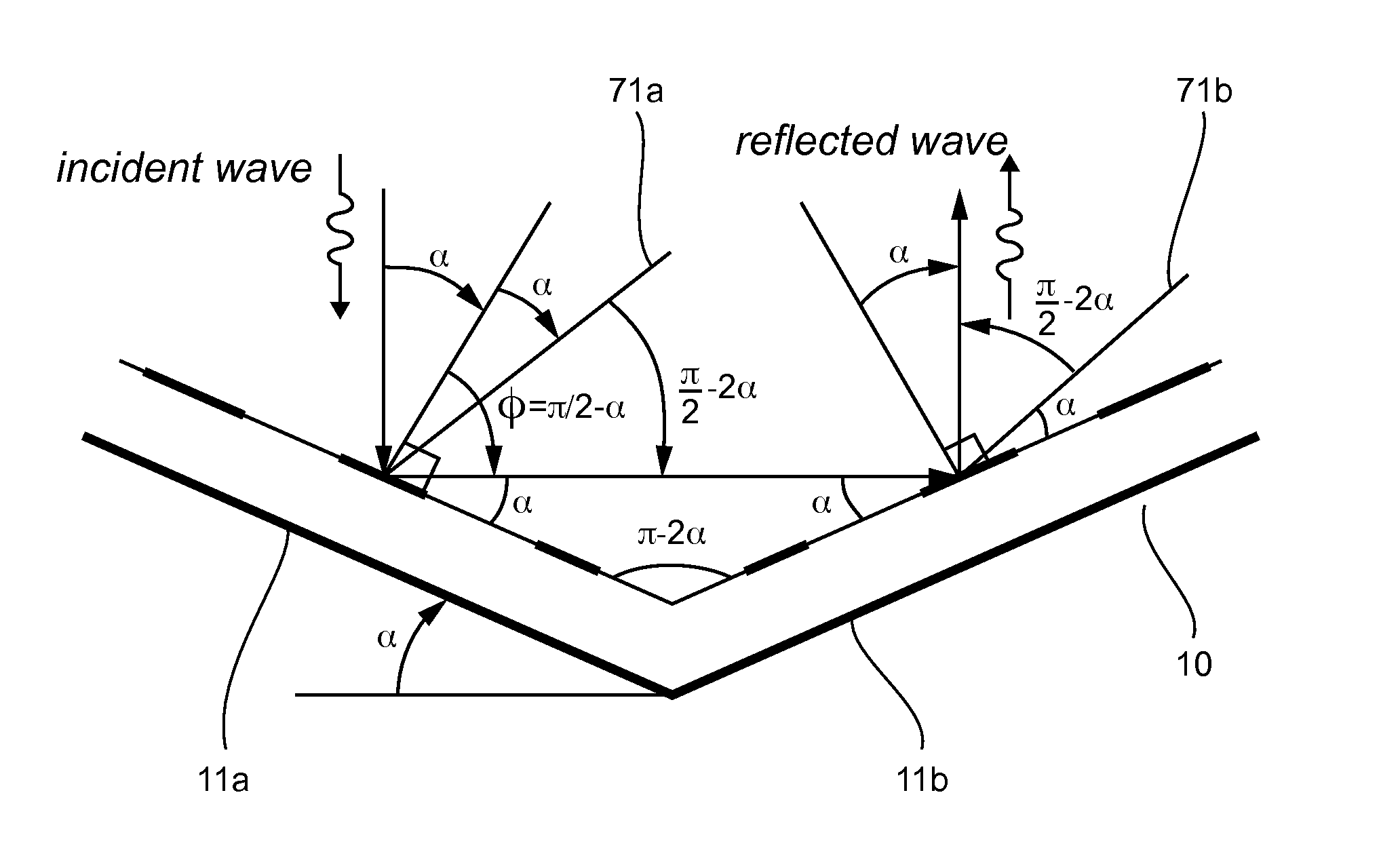
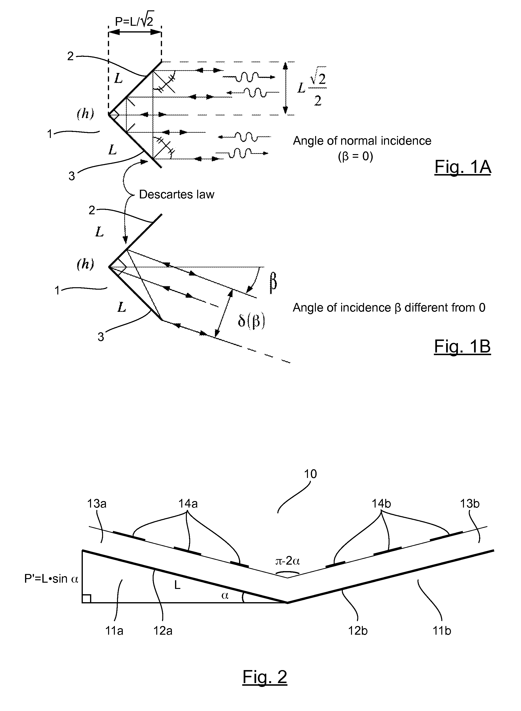
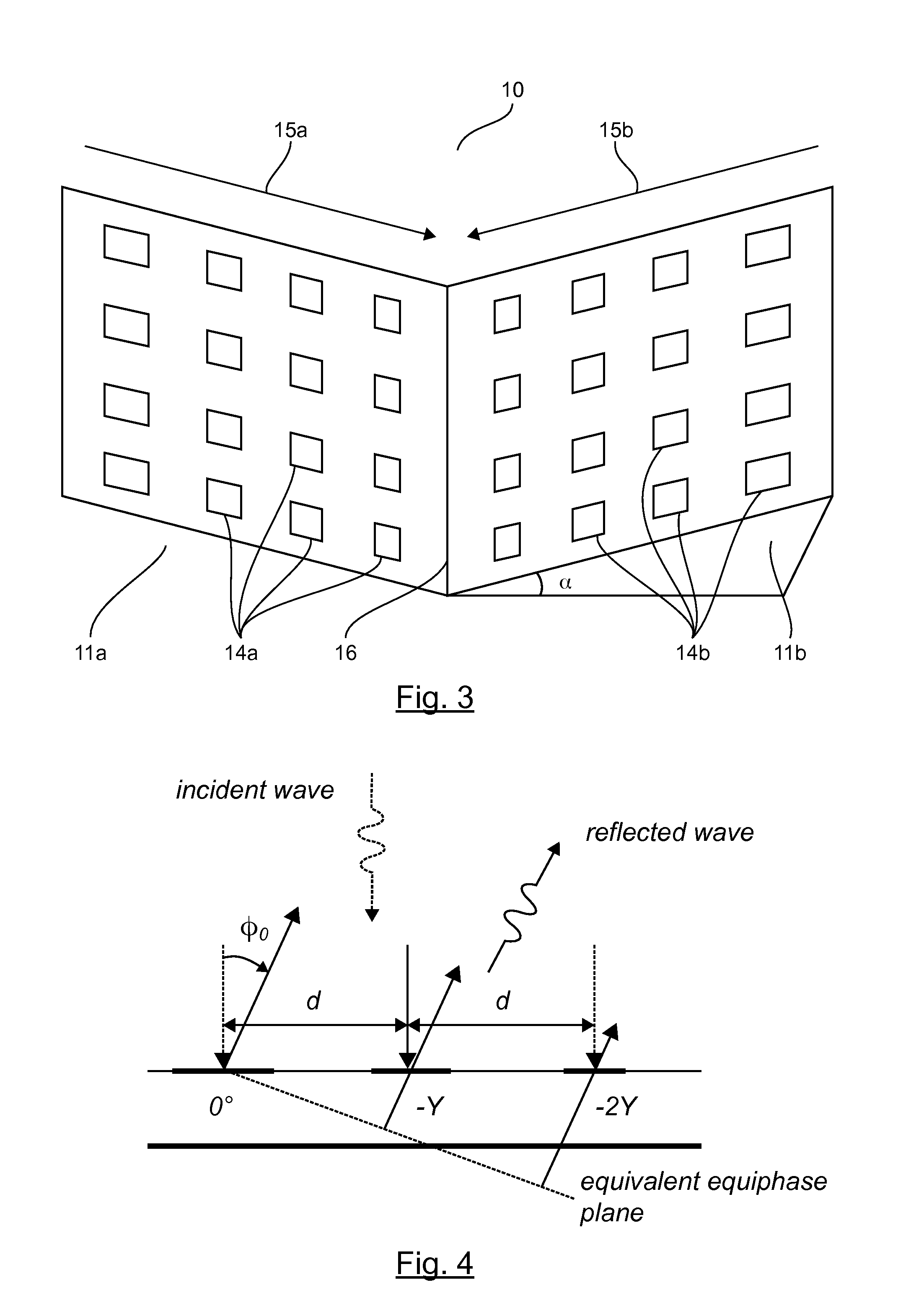
The patent text describes a new device called a dihedral-shaped device that uses two plates with arrays of radiating elements to control the direction of re-radiation of an incident wave. The device forms an angle of π-2α with the two plates. The radiating elements create phase shifts that allow for control of the direction of the re-radiation, regardless of the aperture of the angle. This technology provides a novel and innovative approach to steering the re-radiation of waves.

Problems solved by technology

This first prior-art solution has a major drawback: the two metal plates, having a dimension of L×L for example, must form an angle of n / 2 in order that the double reflection mechanism may be efficient (i.e. in order that it may have an angle of the incident wave that is equal to the angle of the reflected wave).
However, such an array requires printed interconnection lines between the different elements of the array.
These lines cause losses, parasitic radiation and complexity in design.
These structures are more difficult to implement since they are based on an active structure (multiplication with a local oscillator oscillating at a frequency double that of the received signal).
Finally, it is also possible to set up combinations of different types of materials in order that the summation of the waves reflected by each of these materials will be destructive (by the combination of an AMC (Artificial Magnetic Conductor) type structure and a PEC (Perfect Electric Conductor) type structure).

Method used


Image

  • Flattened Dihedral-Shaped Device Possessing an Adapted (Maximized Or Minimized) Equivalent Radar Cross Section
  • Flattened Dihedral-Shaped Device Possessing an Adapted (Maximized Or Minimized) Equivalent Radar Cross Section
  • Flattened Dihedral-Shaped Device Possessing an Adapted (Maximized Or Minimized) Equivalent Radar Cross Section

Examples


case 1 (see fig.5)

[0066]Case 1 (see FIG. 5): the angle of incidence β introduces an additional phase delay relative to the configuration of the wave in normal incidence and the new phase law γ can be written as follows:

γ=k0 d sin (φ)=k0 d sin (φ0)+k0 d sin (β)

[0067]where φ0 corresponds to the deviation of the reflected wave for the wave in normal incidence (see FIG. 4).

case 2 (see fig.6)

[0068]Case 2 (see FIG. 6): the angle of incidence β introduces a phase lead relative to the configuration of the wave in normal incidence and the new phase law γ can be written as follows:

γ=k0 d sin (φ)=k0 d sin (φ0)−k0 d sin (β)

[0069]with the same meaning for the angle φ0 as in the case 1.

6.3 Geometry of the Problem

[0070]FIG. 7 illustrates the operation of the device 10 of FIG. 2 for a plane wave in normal incidence relative to the rear equivalent plane of the device.

[0071]This FIG. 7 therefore describes the geometry of the problem of the dihedron known as the “flattened” dihedron when the incident wave is normal to the equivalent backplane, i.e. when the incident wave forms an angle α with the normal to the surface of the phase shifter array of the left-hand plate 11a (normal of the surface of those plates 11a, of the two plates 11a, 11b that receive the incident wave). This configuration is called the “zero incidence configuration”.

[0072]In this example, we describe the different...


PUM


Abstract

A dihedral shaped device is provided, which includes two plates forming between them an angle of [pi]−2[alpha], where 0<[alpha]<[pi] / 4. Each plate has a ground plane, at least one dielectric layer and a network of radiating elements. An incident wave is reflected by the device by virtue of a double reflection from both plates. The network of radiating elements of each plate allows a phase shift to be generated, from the exterior towards the centre of the dihedron, along an axis perpendicular to an axis of intersection of the two plates, according to a set phase law, allowing a deviation to be introduced relative to a specular reflection for a given operating frequency.

Description

1. CROSS-REFERENCE TO RELATED APPLICATIONS[0001]This Application is a Section 371 National Stage Application of International Application No. PCT / EP2013 / 073306, filed Nov. 7, 2013, the content of which is incorporated herein by reference in its entirety, and published as WO 2014 / 072431 on May 15, 2014, not in English.2. FIELD OF THE INVENTION[0002]The field of the invention is that of dihedral-shaped or dihedral devices comprising two plates.[0003]More specifically, the invention pertains to a technique for adapting (maximizing or minimizing) the equivalent radar cross-section (RCS) in a mono-static configuration of a device having flattened dihedral shape, i.e. a dihedral or dihedron, the two plates of which mutually form an angle of π−2α, with 0<α<π / 4.[0004]The invention can be used especially for any application where it desired to adapt (especially to maximize or minimize) the RCS of an object.[0005]For maximizing the RCS, it is sought to make an object very easily detecta...

Claims


Application Information

Patent Timeline
Patent Type & Authority Applications(United States)
IPC IPC(8): H01Q3/46H01Q15/18
CPCH01Q15/18H01Q3/46H01Q15/0013
Inventor GILLARD, RAPHAELMERIC, STEPHANE
Owner INSTITUT NAT DES SCI APPLIQUEES INSA
Learn More