Antenna

Inactive Publication Date: 2015-09-17
QUALCOMM TECH INT
View PDF3 Cites 1 Cited by
  • Summary
  • Abstract
  • Description
  • Claims
  • Application Information

AI Technical Summary

Benefits of technology

The patent describes a new kind of antenna that is highly directional and has high gain in one direction and low gain in another. This works because a reflector is used to tune the antenna's impedance, which means it doesn't need an extra network to match it to the radio device. The antenna can be made to work over a wide range of frequencies, making it very flexible for different applications. It is also easy to manufacture and small in size, which makes it ideal for use in small devices.

Problems solved by technology

In such an indoor location application, the retail tag must be configured to transmit a signal to a user of the mobile telephone or other compatible device who is standing in an aisle in which the retail tag is deployed, without also transmitting a signal that could be detected by devices in adjacent aisles, as such transmissions could interfere with other retail tags deployed in the adjacent aisles.
Thus, in no plane do existing antennas provide high gain in one direction and low gain in an opposite direction.

Method used


Image

  • Antenna
  • Antenna
  • Antenna

Examples


Embodiment Construction

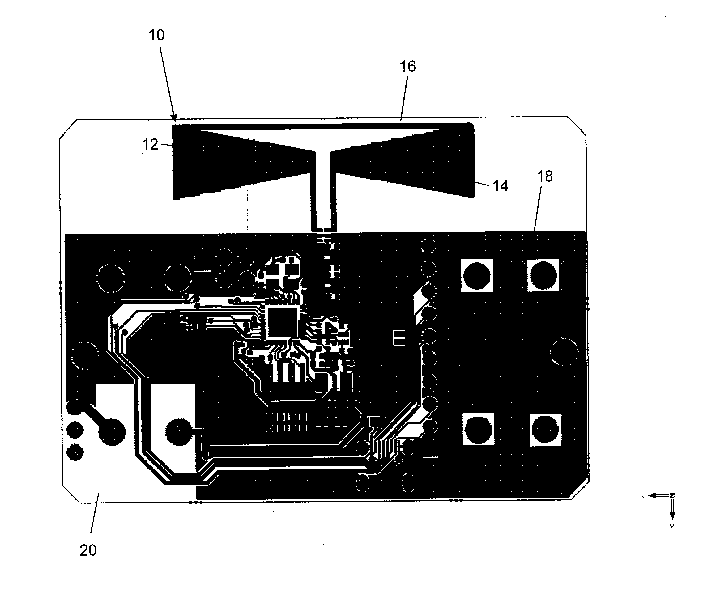
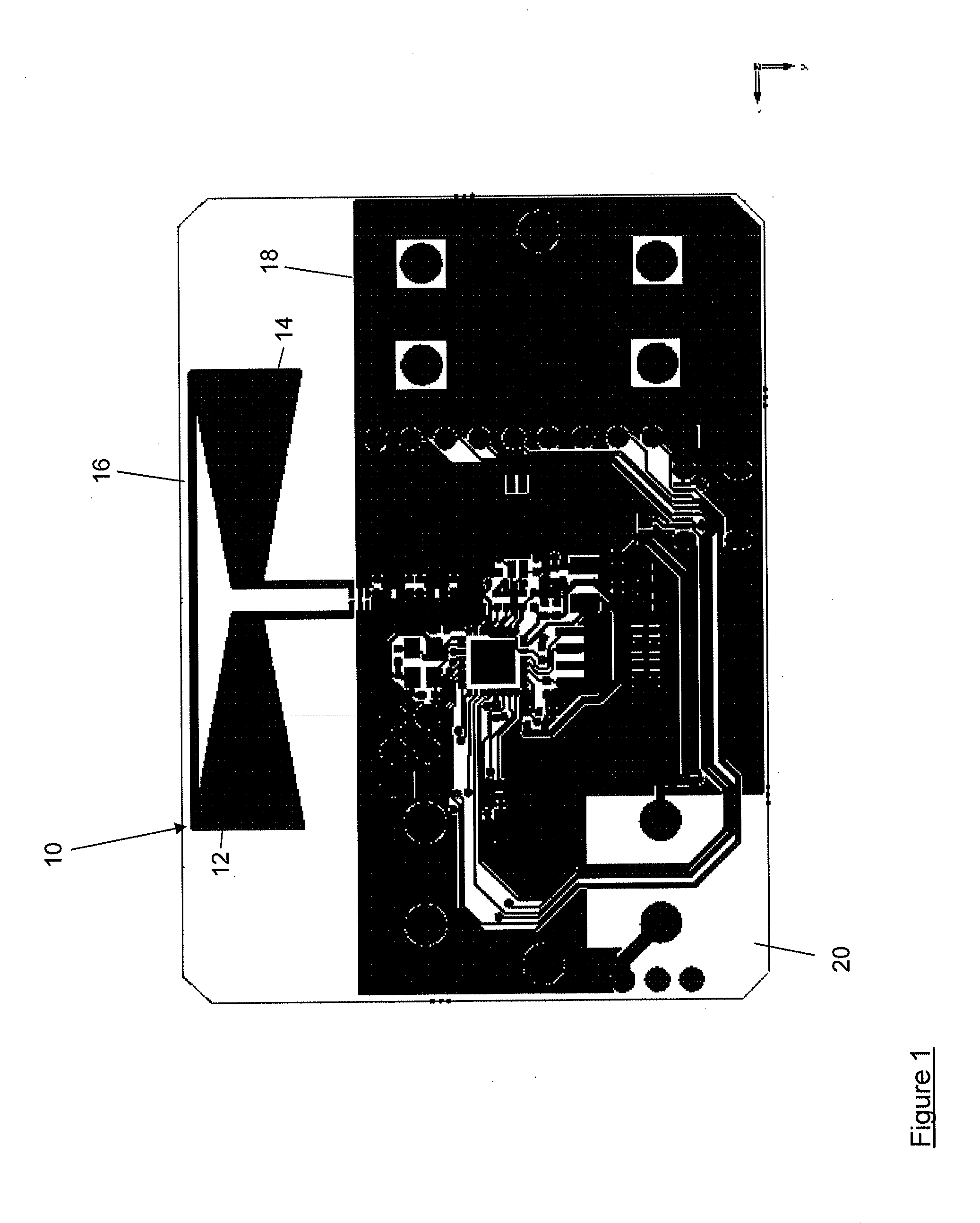
[0033]Referring first to FIG. 1, an antenna is shown generally at 10. The antenna 10 comprises first and second substantially symmetrical electrically conductive antenna elements 12, 14 which are connected by a third conductive antenna element 16 such that the first, second and third electrically conductive antenna elements 12, 14, 16 together form a folded dipole antenna. In the exemplary embodiment illustrated in FIG. 1, the folded dipole antenna takes the form of a folded bow-tie dipole. As will be understood by those skilled in the art, a bow-tie dipole is a form of dipole antenna which uses two opposed antenna elements which are thicker at their ends where the electric field is strongest. This thickening of the antenna elements at the ends creates a distinctive structure which resembles a bow-tie.

[0034]The third antenna element 16 electrically connects the first and second antenna elements 12, 14, thus changing the bow-tie configuration provided by the first and second antenna ...


PUM


Abstract

An antenna comprising: a folded dipole and a reflector positioned to reflect radiation emitted by the dipole that is incident on the reflector.

Description

TECHNICAL FIELD[0001]The present invention relates to an antenna.BACKGROUND TO THE INVENTION[0002]Some applications require an antenna with high directionality, that is to say a high gain in one direction, and low gain in opposite directions. For example, in a retail environment such as a supermarket, a retail tag may be deployed on a shelf to provide highly localised product information or advertising to compatible devices such as mobile telephones and the like. In such an indoor location application, the retail tag must be configured to transmit a signal to a user of the mobile telephone or other compatible device who is standing in an aisle in which the retail tag is deployed, without also transmitting a signal that could be detected by devices in adjacent aisles, as such transmissions could interfere with other retail tags deployed in the adjacent aisles. In such applications, a highly directional antenna is required in the retail tag, to minimise or at least reduce such “zone-b...

Claims


Application Information

Patent Timeline
IPC IPC(8): H01Q9/26H01Q19/10H01Q9/28
CPCH01Q9/26H01Q19/108H01Q9/285H01Q23/00H01Q9/065
Inventor SMITH, LESLIE DAVID
Owner QUALCOMM TECH INT
Why Eureka
Try Eureka