Method and an apparatus for controlling grain size of a component

a technology of component grain size and control method, which is applied in the field of additive manufacturing, can solve the problems of small grain size in a solidified component, limited time for solidification of melted powder layer, and rapid solidification

Inactive Publication Date: 2015-09-24
SIEMENS AG
View PDF1 Cites 26 Cited by
  • Summary
  • Abstract
  • Description
  • Claims
  • Application Information

AI Technical Summary

Benefits of technology

[0012]The advantage of the invention is that, the grain size of the component can be controlled by varying the thickness of the layers that are used to construct the component and the amount of compressive residual stress induced in the layers during the construction the component. The post heat treatment grain size of the component with stress induced layers is significantly larger than a component manufactured using an AM process without inducing strain.
[0013]Further, the control of the grain size of the component can be achieved by choosing the right material to construct the component. The grain size can also be controlled by the level of stress induced the layers while constructing the component. Furthermore, the grain size also depends on the time and temperature at which the component is heated for initiating recrystallization and grain growth.
[0014]In an embodiment of the invention, the stress is introduced in the component by mechanical deformation of the component. In some embodiments, the grain size is a function of the thickness T1 of the plurality of layers constituting the component.
[0015]In accordance with an embodiment of the invention, the fusible material is at least one of a nickel based superalloy and a cobalt based superalloy. The component is designed to be used in turbomachinery where the component is exposed to extreme temperatures. The nickel and cobalt based superalloys are capable of withstanding extreme heat.
[0016]In an aspect of the present invention, an apparatus for generating a component having a controllable a grain size using an additive manufacturing process is disclosed. The apparatus includes a construction unit, wherein the construction unit generates a first fused layer of the component by fusing a plurality of layers of a fusible material using a heat source, wherein the first fused layer has a thickness T1.
[0017]In a further aspect of the present invention, the apparatus comprises a stress inducing unit, wherein the stress inducing unit introduces stress through the first fused layer. The stress inducing unit is configured to introduce stress into the component which aids in controlling the grain size of the component. Furthermore, the apparatus includes a heat treatment unit for heating the component at a temperature above recrystallization start temperature (Rxst) to control the grain size of the component. The heat treatment unit may vary the temperature in order to modify the grain size of the component.

Problems solved by technology

This leads to rapid solidification once the beam moves to another point on the layer.
The time for solidification of a melted powder layer is limited, and the grain size in a solidified component is very small.
Components with small grain size, such as those manufactured using AM techniques, deteriorate quickly due the effects of creep, stress rupture and thermo mechanical fatigue (TMF) and the like.

Method used


Image

  • Method and an apparatus for controlling grain size of a component
  • Method and an apparatus for controlling grain size of a component
  • Method and an apparatus for controlling grain size of a component

Examples


Embodiment Construction

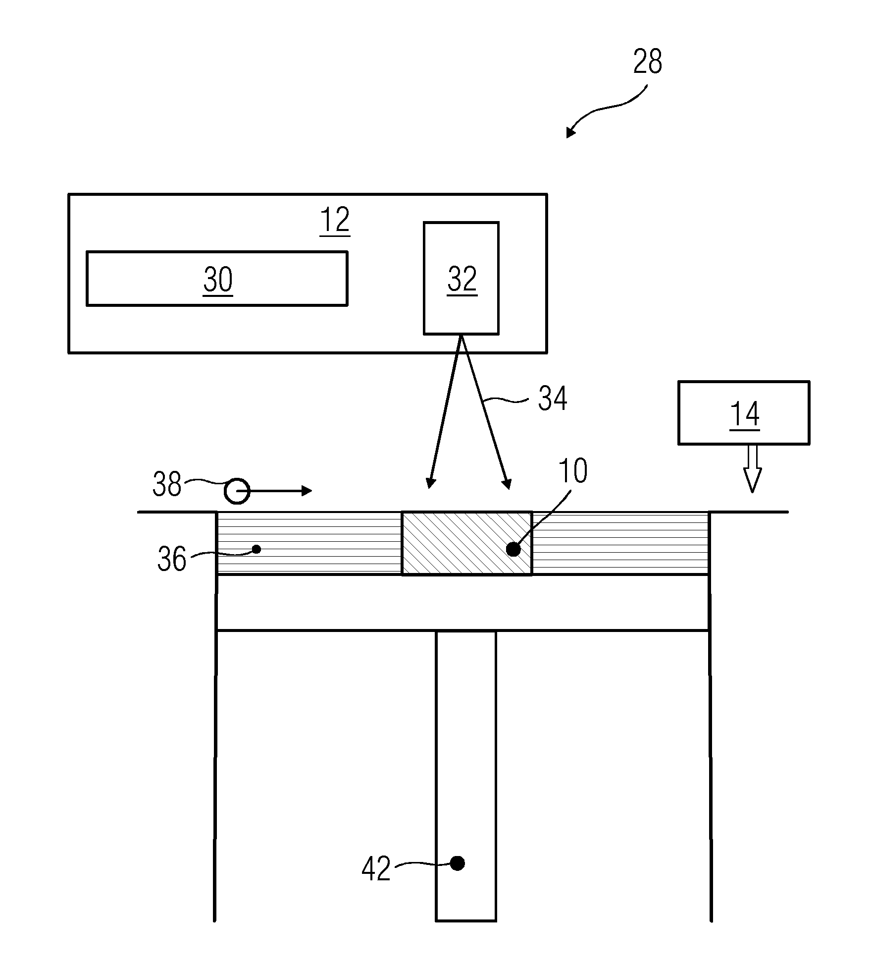
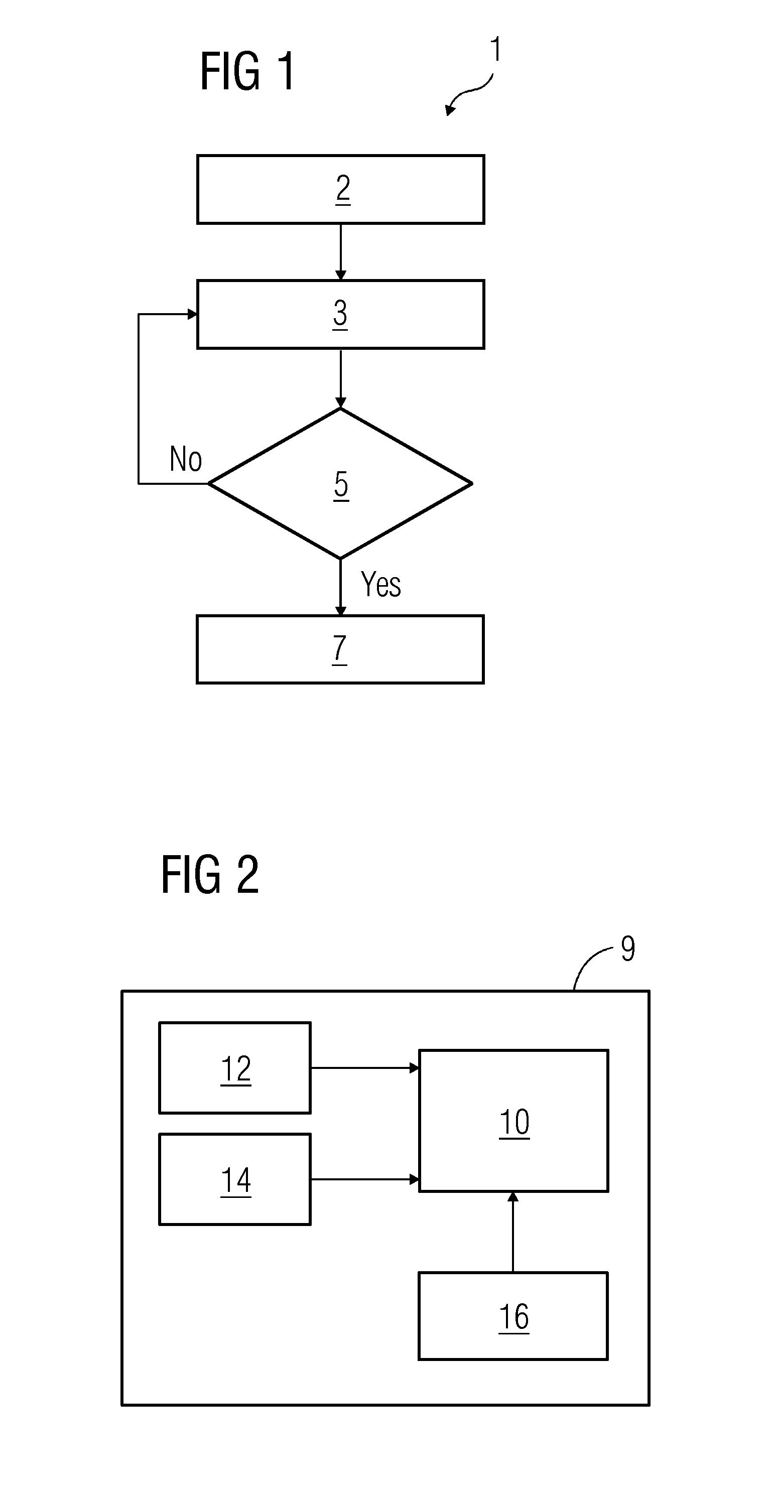
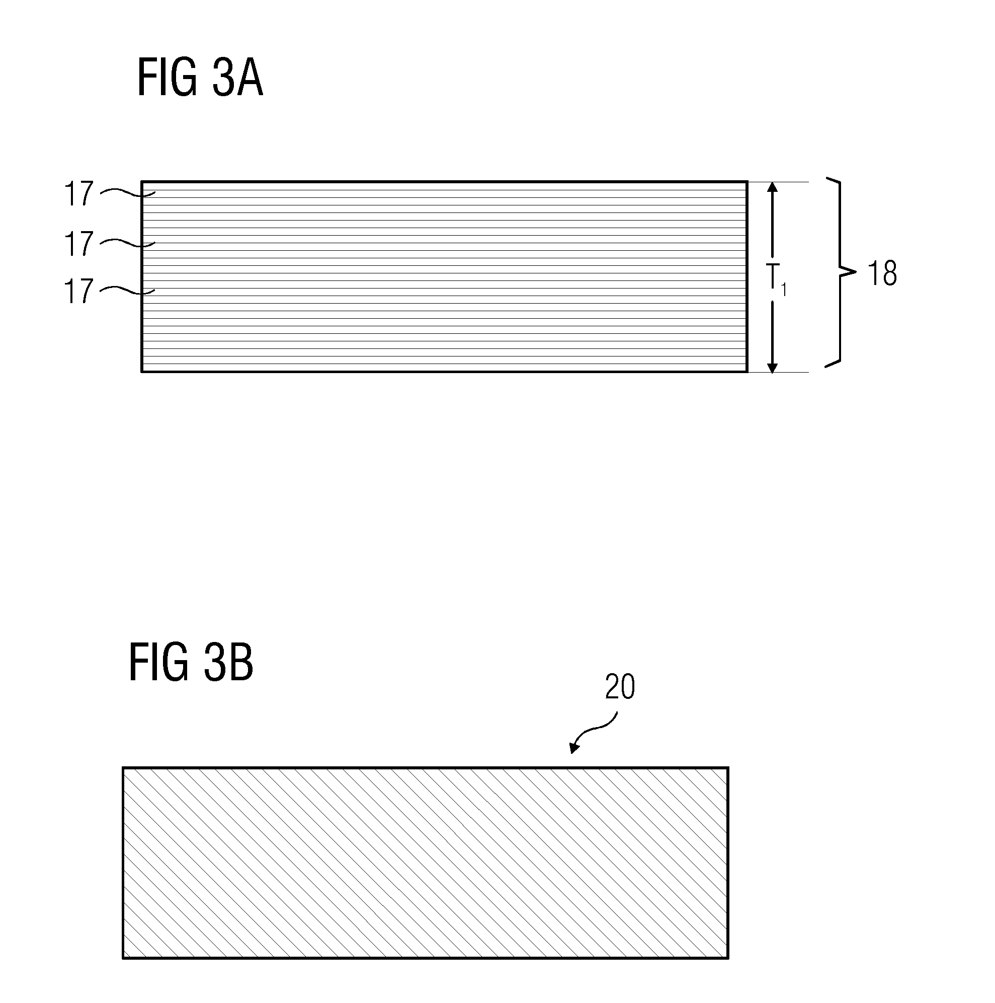
[0024]FIG. 1 illustrates a flow diagram of an exemplary method of controlling a grain size of a component generated using an additive manufacturing (AM) process. The AM process can include at least one of selective laser melting (SLM), electron beam melting (EBM), laser metal forming (LMF), laser engineered net shape (LENS), or direct metal deposition (DMD). At step 2, a first fused layer of the component is constructed by fusing a plurality of layers of a fusible material using a heat source. The plurality of layers of fusible materials may be, for example, a powdered metal or alloy. The heat source used to fuse the plurality of layers may be a high powered laser source. In some embodiments, the heat source may be an electric arc. The heat source is directed to melt specific quantities of the layers of material in order to fuse them to generate a first fused layer of the component. The first fused layer of the component has a thickness T1. The thickness T1 of the first fused layer ...


PUM

PropertyMeasurementUnit
grain sizeaaaaaaaaaa
thickness T1aaaaaaaaaa
stressaaaaaaaaaa

Abstract

A method and an apparatus for controlling a grain size of a component generated using an additive manufacturing process. Construct a first fused layer of the component by fusing a plurality of layers of a fusible material, wherein the first fused layer has a thickness T1. Thereafter, introduce stress through the first fused layer of the component. The component is generated by repeating the aforementioned steps. Further, the component is heated to a temperature above a recrystallization start temperature (Rxst) to control the grain size of the component.

Description

FIELD OF THE INVENTION[0001]This invention relates to a field of additive manufacturing and in particular, to a method and an apparatus for controlling a grain size of a component manufactured using an additive manufacturing process.BACKGROUND OF THE INVENTION[0002]In additive manufacturing techniques, a heat source is used to melt a specified amount of metal, which is in the form of a powder or wire, onto a base material. By repeating the process, layers of melted metallic powder are each arranged sequentially upon a preceding layer, resulting in the formation of a desired component. Additive manufacturing (AM) techniques can include selective laser melting (SLM), electron beam melting (EBM), laser metal forming (LMF), laser engineered net shape (LENS), or direct metal deposition (DMD). The invention is related mainly to the SLM additive manufacturing technique.[0003]In the SLM technique, a laser beam scans a layer filled with metal or plastic powder, thereby melting and solidifyin...

Claims


Application Information

Patent Timeline
Patent Type & Authority Applications(United States)
IPC IPC(8): B23K26/34B23K26/00B22F3/24B22F3/105
CPCB33Y40/00B22F3/24B22F3/1055B23K26/345B22F2301/15B33Y10/00B33Y30/00B22F2003/248B22F2003/1056B23K26/0093B22F2998/10B29C64/153B29C64/188Y02P10/25B22F10/64B22F10/28B22F10/38B22F10/25B33Y40/20B22F3/168
Inventor JAMES, ALLISTER WILLIAMOTT, MICHAEL
Owner SIEMENS AG
Why Eureka
Try Eureka