
Methods of manufacturing blades of turbomachines by wire electric discharge machining, blades and turbomachines

a technology of turbomachines and blades, which is applied in the direction of liquid fuel engines, vessel construction, marine propulsion, etc., can solve the problems of sacrificing shape and/or size precision, affecting the quality of blades, and rotor blade damage, etc., to achieve the effect of reducing manufacturing costs and facilitating and more economical manufacturing

Inactive Publication Date: 2015-09-24
NUOVO PIGNONE SPA
View PDF6 Cites 7 Cited by
  • Summary
  • Abstract
  • Description
  • Claims
  • Application Information

AI Technical Summary

Benefits of technology

The patent discusses a need for a better and more economical way to manufacture steam turbine blades without sacrificing their shape and size precision. The solution proposed involves a single-piece blade design, using milling to achieve precise shape and a wire EDM process for the internal cavity. This method requires no welding and achieves high precision in the machine surface. Additionally, the blade's lateral wall can have a low thickness. Overall, this patent presents a solution for manufacturing steam turbine blades that is simpler, more precise, and cost-effective.

Problems solved by technology

If droplets are generated as a consequence of condensation, they leave the static stator blades and they hit the rotating rotor blades; therefore, damages to the rotor blades may occur.
Anyway, it is quite expensive as the milling operation (for the inside and the outside) is relatively slow.
These hollow blades are typically obtained through casting, particularly “investment casting”, in order to obtain a rotating element having an extremely precise shape and size; anyway, this manufacturing method is very expensive especially when used for small-lot production (for example 100-1000 pieces).

Method used


Image

  • Methods of manufacturing blades of turbomachines by wire electric discharge machining, blades and turbomachines
  • Methods of manufacturing blades of turbomachines by wire electric discharge machining, blades and turbomachines
  • Methods of manufacturing blades of turbomachines by wire electric discharge machining, blades and turbomachines

Examples


Embodiment Construction

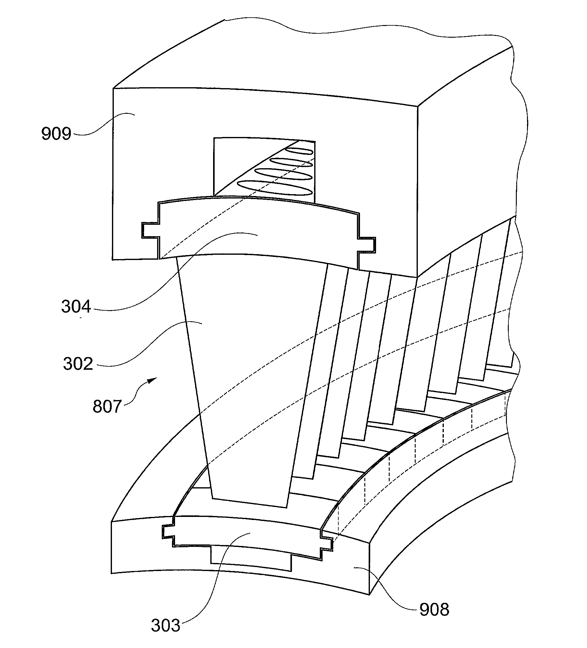
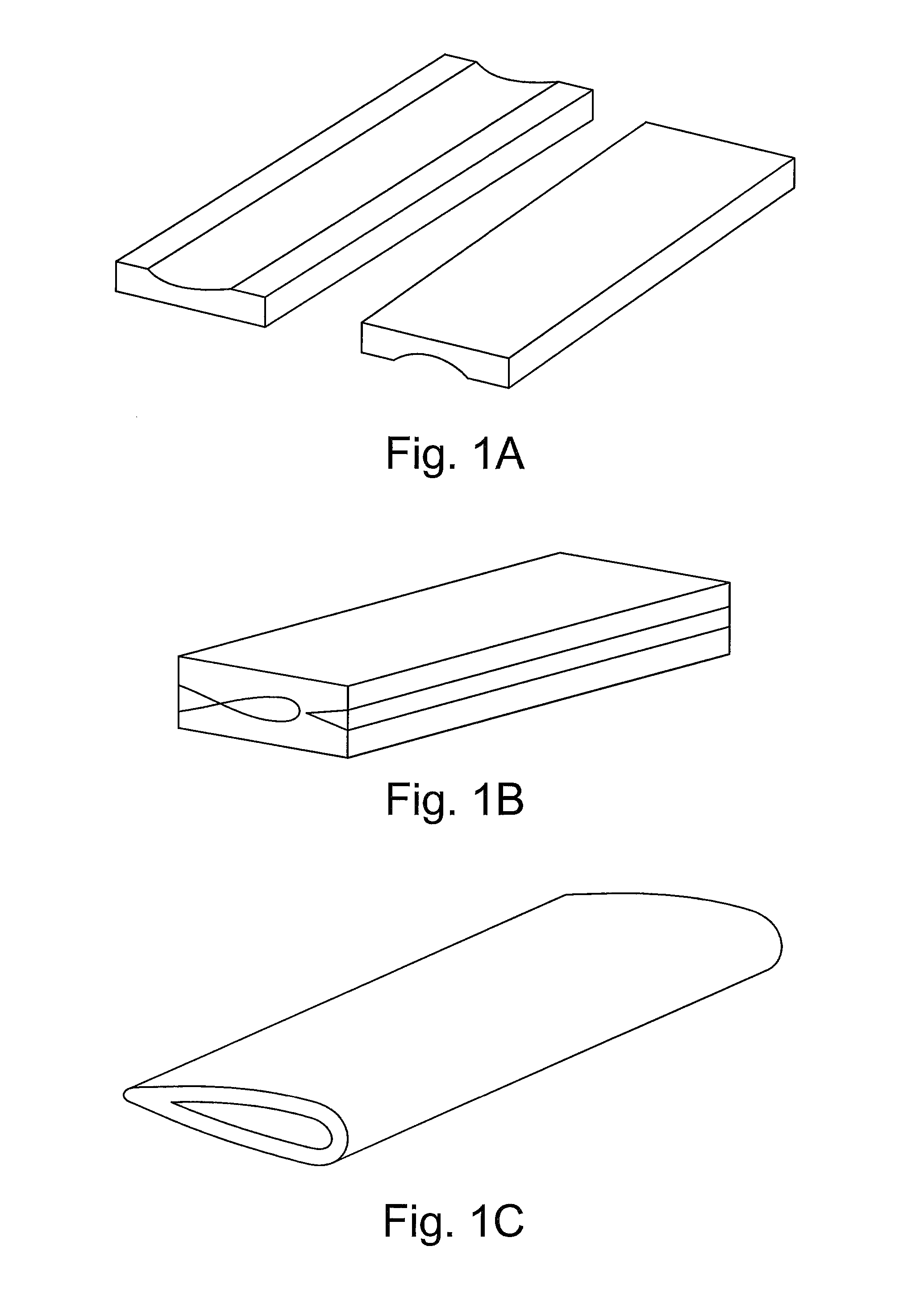
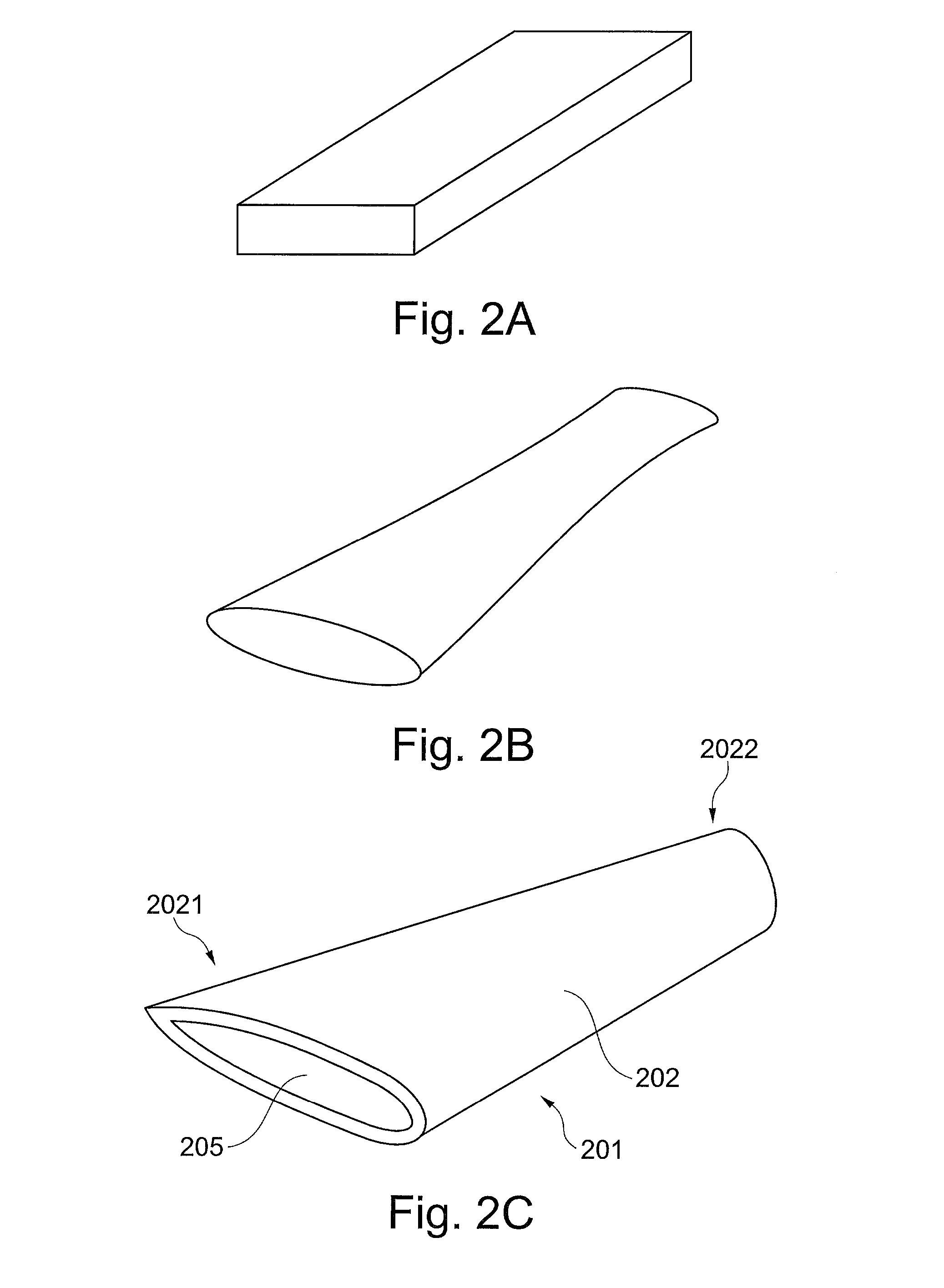
[0088]The following description of the exemplary embodiments refers to the accompanying drawings. The same reference numbers in different drawings identify the same or similar elements. The following detailed description does not limit the invention. Instead, the scope of the invention is defined by the appended claims.

[0089]It is to be noted that in the accompanying drawings sometimes sizes have been exaggerated for the sake of clarity; in other words they are not perfectly in scale between each other.

[0090]Reference throughout the specification to “one embodiment” or “an embodiment” means that a particular feature, structure, or characteristic described in connection with an embodiment is included in at least one embodiment of the subject matter disclosed. Thus, the appearance of the phrases “in one embodiment” or “in an embodiment” in various places throughout the specification is not necessarily referring to the same embodiment. Further, the particular features, structures or ch...


PUM

PropertyMeasurementUnit
Lengthaaaaaaaaaa
Shapeaaaaaaaaaa
Distanceaaaaaaaaaa

Abstract

The method is used for manufacturing a blade of a turbomachine comprising an airfoil portion; according thereto at least one external or internal surface of the airfoil portion is obtained by wire electric discharge machining; this is allowed by designing these surfaces as “ruled surfaces” or very close to such kind of surfaces; this method is particularly effective, for forming internal cavities of hollow stator blades of steam turbines; this method allows to manufacture in a single piece hollow blades having root portions and shroud portions. Blade of a turbomachine with an internal cavity wherein the surface of the airfoil of the blade inside the cavity defines grooves perpendicular to the axis of the turbomachine.

Description

BACKGROUND OF THE INVENTION[0001]Embodiments of the subject matter disclosed herein generally relate to blades for turbomachines, turbomachines using such blades and methods of manufacturing such blades; more specifically, they relate to stator blades for steam turbines, steam turbines using such blades and methods of manufacturing such blades.[0002]In steam turbines, partial condensation of the steam occurs at their last stage or stages.[0003]In particular condensation occurs on the airfoil portion of the stator blades of a so-called “condensing stage”, typically the last stage of the turbine.[0004]If droplets are generated as a consequence of condensation, they leave the static stator blades and they hit the rotating rotor blades; therefore, damages to the rotor blades may occur.[0005]In order to reduce the damages caused by the droplets, the rotation speed of the rotor blades may be reduced; but in this way, the efficiency of the turbine is also reduced.[0006]Alternatively, in or...

Claims


Application Information

Patent Timeline
IPC IPC(8): F01D5/14B23H9/10B23H7/02F01D5/18
CPCF01D5/147B23H7/02B23H9/10F01D5/18B23H1/00B23P15/04F01D9/02
Inventor GRILLI, MARCOARCIONI, MASSIMOGIUSTI, ENRICOCECCONI, MASSIMILIANO
Owner NUOVO PIGNONE SPA
Learn More