Laser-type gas analyzer

a gas analyzer and gas type technology, applied in the field of gas type analyzers, can solve the problems of limited gas types of gas analyzers, hcl+hsub>2/sub>o, or the like, and achieve the effect of high precision

Active Publication Date: 2015-09-24
FUJI ELECTRIC CO LTD
View PDF5 Cites 20 Cited by
  • Summary
  • Abstract
  • Description
  • Claims
  • Application Information

AI Technical Summary

Benefits of technology

[0051]The present invention succeeds in providing a laser-type gas analyzer that can measure, with high precision and using one single device, the gas concentration of a first gas to be measured in a mid-infrared region, and the gas concentration of a second gas to be measured in a near-infrared region, even in a measurement environment where dust and water at a high concentration are present.

Problems solved by technology

However, most conventional laser-type gas analyzers can measure one type of gas to be measured per device, while laser-type gas analyzers that can detect the concentration of two or more types of gas, for instance CO+CO2, NH3+H2O, HCl+H2O, or the like, are limited as regards the types of gas.
The cost of the analyzers and construction costs increase as a result.
This is compounded with the problem of the increased equipment size.
This was problematic in that, with a light amount decrease due to dust being of DC type, it was difficult to discriminate between absorption by the gas to be measured and light amount attenuation by dust, and to measure accurately gas concentrations by correcting received light amounts, when measuring a gas such as SO2 gas.
Further problems arise when water is present in the exhaust gas in a substantial amount.
It is therefore very difficult to measure SO2 gas concentration by excluding the optical absorption spectrum of water.
This is problematic in that the received light amount is attenuated due to such an influence.
As a result, a problem arises thus in a conventional laser-type gas analyzer in that when water is present in the space to be measured, the measured value of the gas to be measured becomes attenuated, and the gas concentration cannot be measured accurately.
Similar problems arise when measuring the gas concentration of a first gas to be measured in a mid-infrared region, such as SO2 gas, and the gas concentration of a second gas to be measured in a near-infrared region, such as CO2 gas.

Method used


Image

  • Laser-type gas analyzer
  • Laser-type gas analyzer
  • Laser-type gas analyzer

Examples


Embodiment Construction

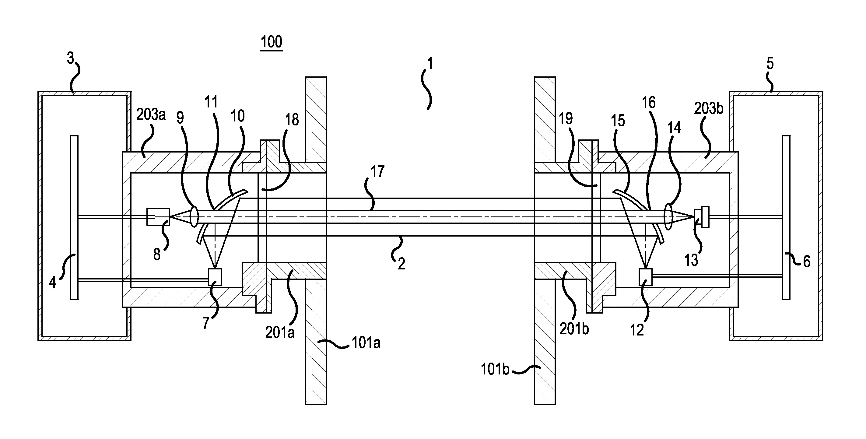
[0080]Embodiments of the present invention will be explained next with reference to accompanying drawings. As a specific example, the laser-type gas analyzer in the embodiments is a device that analyzes SO2 gas concentration and CO2 gas concentration in marine exhaust gas, wherein a first gas to be measured is SO2 gas, and a second gas to be measured is CO2 gas. The laser-type gas analyzer can measure SO2 gas concentration using a mid-infrared laser light-emitting unit and can measure CO2 gas concentration using a near-infrared laser light-emitting unit, while nullifying the influence of water present in the space to be measured and the influence of dust present in the space to be measured, in an environment where dust and water at a high concentration are present, such as marine exhaust gas. The laser-type gas analyzer measures thus, with high precision, the targeted gas concentrations.

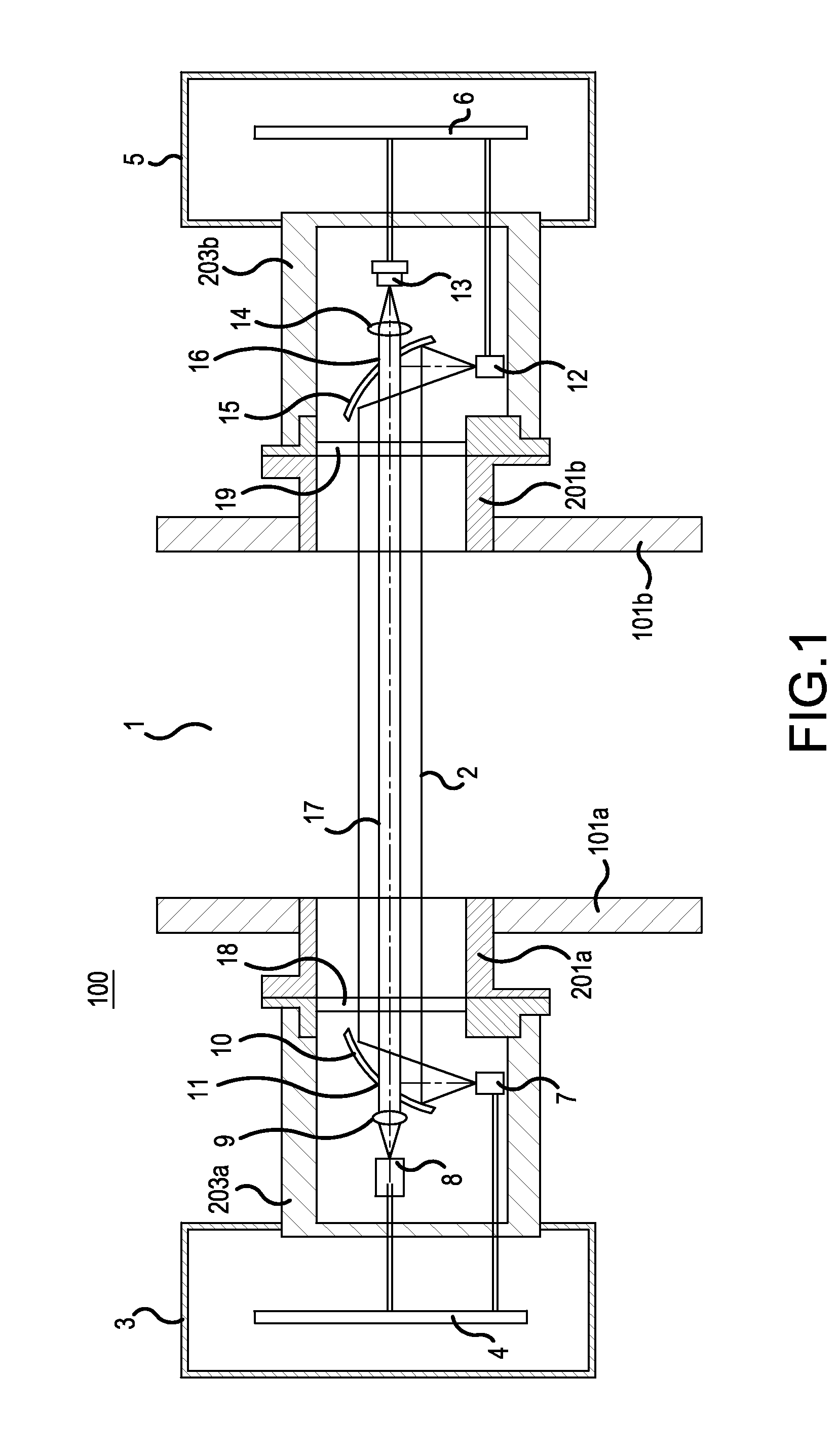
[0081]Firstly, FIG. 1 illustrates the overall configuration of a laser-type gas analyzer accordin...


PUM

PropertyMeasurementUnit
wavelengthaaaaaaaaaa
wavelength rangingaaaaaaaaaa

Abstract

Aspects of a laser-type gas analyzer can include a mid-infrared light reception signal processing and computing unit that calculates a gas concentration of the first gas to be measured on the basis of a mid-infrared light reception signal, a near-infrared light reception signal processing and computing unit that detects, at respective times, the gas concentration of the second gas to be measured, water concentration in a space, and alight amount decrement due to dust, on the basis of near-infrared light reception signal. Also included can be a gas concentration correcting unit that corrects the gas concentrations of the first and second gases to be measured using the water concentration and the light amount decrement.

Description

CROSS-REFERENCE TO RELATED APPLICATIONS[0001]This application is a continuation of International Application No. PCT / JP 2013 / 080634, filed on Nov. 13, 2013, which is based on and claims priority to Japanese Patent Application No. JP 2013-003511, filed on Jan. 11, 2013. The disclosure of the Japanese priority application and the PCT application in their entirety, including the drawings, claims, and the specification thereof, are incorporated herein by reference.BACKGROUND[0002]1. Field of the Invention[0003]The present invention relates to a laser-type gas analyzer that measures, by laser light, the gas concentration of various types of gas in flues.[0004]2. Related Art[0005]As is known, gas atoms and molecules have unique optical absorption spectra. For instance, FIG. 20 illustrates the optical absorption spectrum of ammonia (NH3). The abscissa axis of the graph represents wavelength, and the ordinate axis represents optical absorption intensity.[0006]Laser-type gas analyzers are kn...

Claims


Application Information

Patent Timeline
Patent Type & Authority Applications(United States)
IPC IPC(8): G01N21/3504G01N21/359G01N21/31
CPCG01N21/3504G01N2201/0612G01N21/359G01N21/3103G01N21/3151G01N21/39
Inventor TABARU, MASAYAKOIZUMI, KAZUHIROKONISHI, HIDEYUKIINUI, TAKASHI
Owner FUJI ELECTRIC CO LTD
Why Eureka
Try Eureka