Method and magnetic resonance system for fat saturation

Active Publication Date: 2015-09-24
SIEMENS HEALTHCARE GMBH
View PDF4 Cites 4 Cited by
  • Summary
  • Abstract
  • Description
  • Claims
  • Application Information

AI Technical Summary

Problems solved by technology

When the MR data are acquired in slices, significantly poorer fat saturation may occur as a function of particular measurement parameters in the case of a slice acquired first in time compared to the slic

Method used


Image

  • Method and magnetic resonance system for fat saturation
  • Method and magnetic resonance system for fat saturation
  • Method and magnetic resonance system for fat saturation

Examples


Example

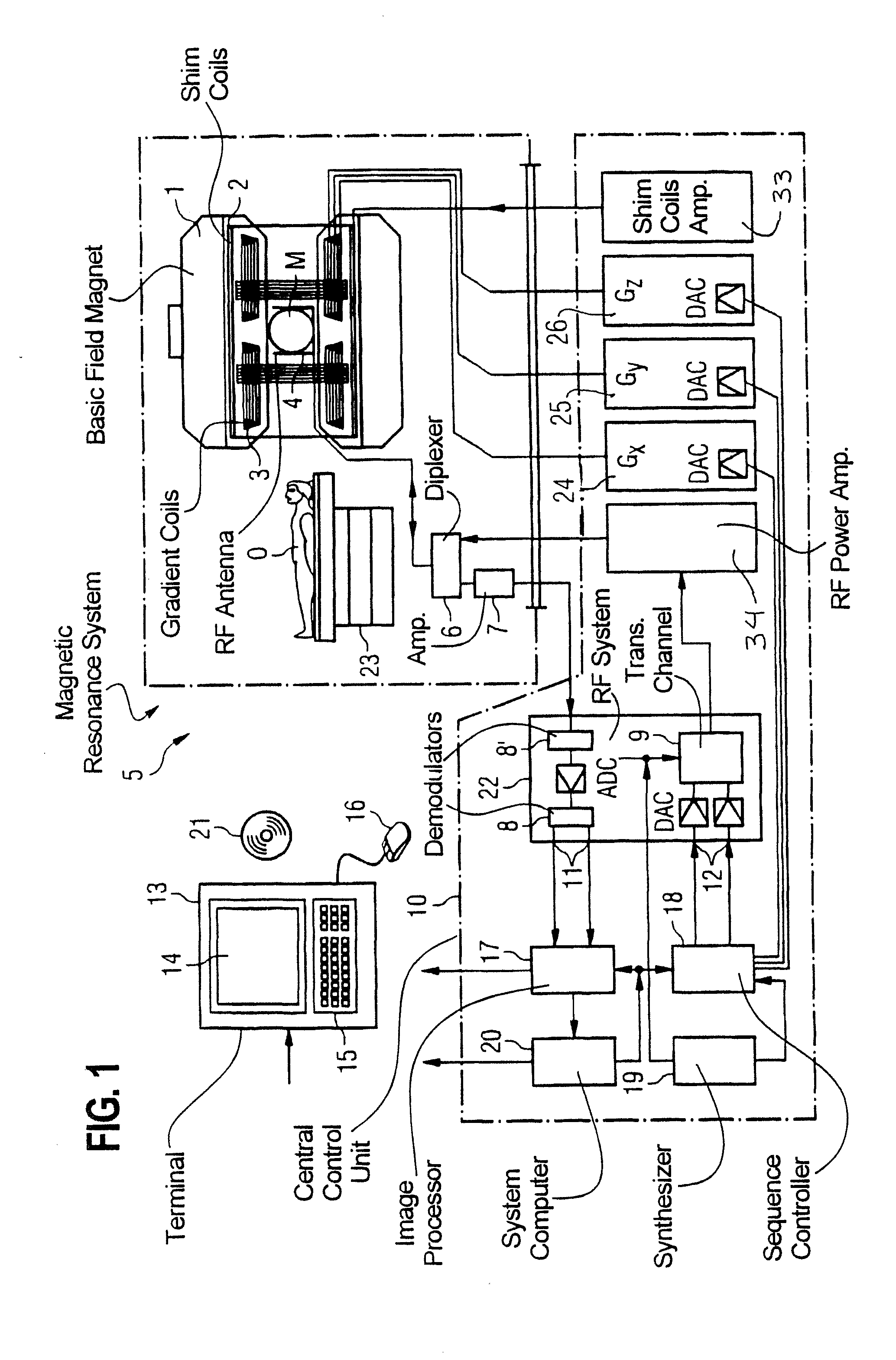
[0055]FIG. 1 is a schematic illustration of a magnetic resonance system 5 (a magnetic resonance imaging or nuclear spin tomography device). Here a basic field magnet 1 generates a strong magnetic field which is constant over time for polarization or orientation of the nuclear spins in an examination region of an object O, such as for example a part to be examined of a human body, which while lying on a table 23 is examined in the magnetic resonance system 5. The high level of homogeneity of the basic magnetic field needed for the nuclear spin resonance measurement is defined in a typically spherical measurement volume M, through which the parts to be examined of the human body are continuously pushed. To support the requirements for homogeneity and in particular to eliminate influences which are invariable over time the so-called shim sheets made of ferromagnetic material are attached at a suitable point. Influences which are variable over time are eliminated by shim coils 2, suppli...


PUM


Abstract

In a method and a magnetic resonance (MR) system for fat saturation when acquiring MR data in a predetermined volume segment of an examination object (O), a flip angle is determined as a function of a predetermined requirement for a fat signal that is acquired by the magnetic resonance system in the volume segment, and an RF preparation pulse is emitted that has the determined flip angle. This is followed by emission of a SPAIR pulse, followed by acquisition of the MR data.

Description

BACKGROUND OF THE INVENTION[0001]1. Field of the Invention[0002]The present invention relates to a method and a magnetic resonance system, in order to perform fat saturation when acquiring MR data.[0003]2. Description of the Prior Art[0004]Several methods for fat saturation are known, including a method that operates with a so-called SPAIR pulse. The SPAIR pulse (“Spectrally Adiabatic Inversion Recovery”) is a frequency-selective adiabatic inversion pulse that is emitted in order to invert only spins of the fat tissue. The actual RF excitation pulse is emitted a particular time period TI after the SPAIR pulse. Conventionally the time period TI is selected such that the longitudinal magnetization of the spins of the fat tissue has as little effect as possible when the MR data is acquired.[0005]When the MR data are acquired in slices, significantly poorer fat saturation may occur as a function of particular measurement parameters in the case of a slice acquired first in time compared ...

Claims


Application Information

Patent Timeline
IPC IPC(8): G01R33/48G01R33/20
CPCG01R33/20G01R33/4828G01R33/4835G01R33/5607
Inventor BLUMHAGEN, JAN OLEPAUL, DOMINIK
Owner SIEMENS HEALTHCARE GMBH
Why Eureka
Try Eureka