Drill rig and methods for directional drilling

a drilling rig and directional drilling technology, applied in the field of civil engineering, can solve the problems of unsuitable above-mentioned methods, the device cannot be protected from shocks and vibrations transmitted by the drill, etc., and achieve the effect of speeding up directional drilling

Inactive Publication Date: 2015-10-01
TREVI
View PDF13 Cites 11 Cited by
  • Summary
  • Abstract
  • Description
  • Claims
  • Application Information

AI Technical Summary

Benefits of technology

[0010]The present invention aims at speeding up a directional drilling, eliminating some of the steps mentioned herein above. Another object of the invention is to keep the inclination measuring device within the string during the drilling while preserving the device from vibrations and shocks transmitted from the drill string.

Problems solved by technology

Unless special shock absorbers are used, this method does not preserve the device from shocks and vibrations transmitted from the drill.
However, the above method is unsuitable if inclination data are needed in real time, for example, to promptly correct the direction of the drilling.

Method used


Image

  • Drill rig and methods for directional drilling
  • Drill rig and methods for directional drilling
  • Drill rig and methods for directional drilling

Examples


Embodiment Construction

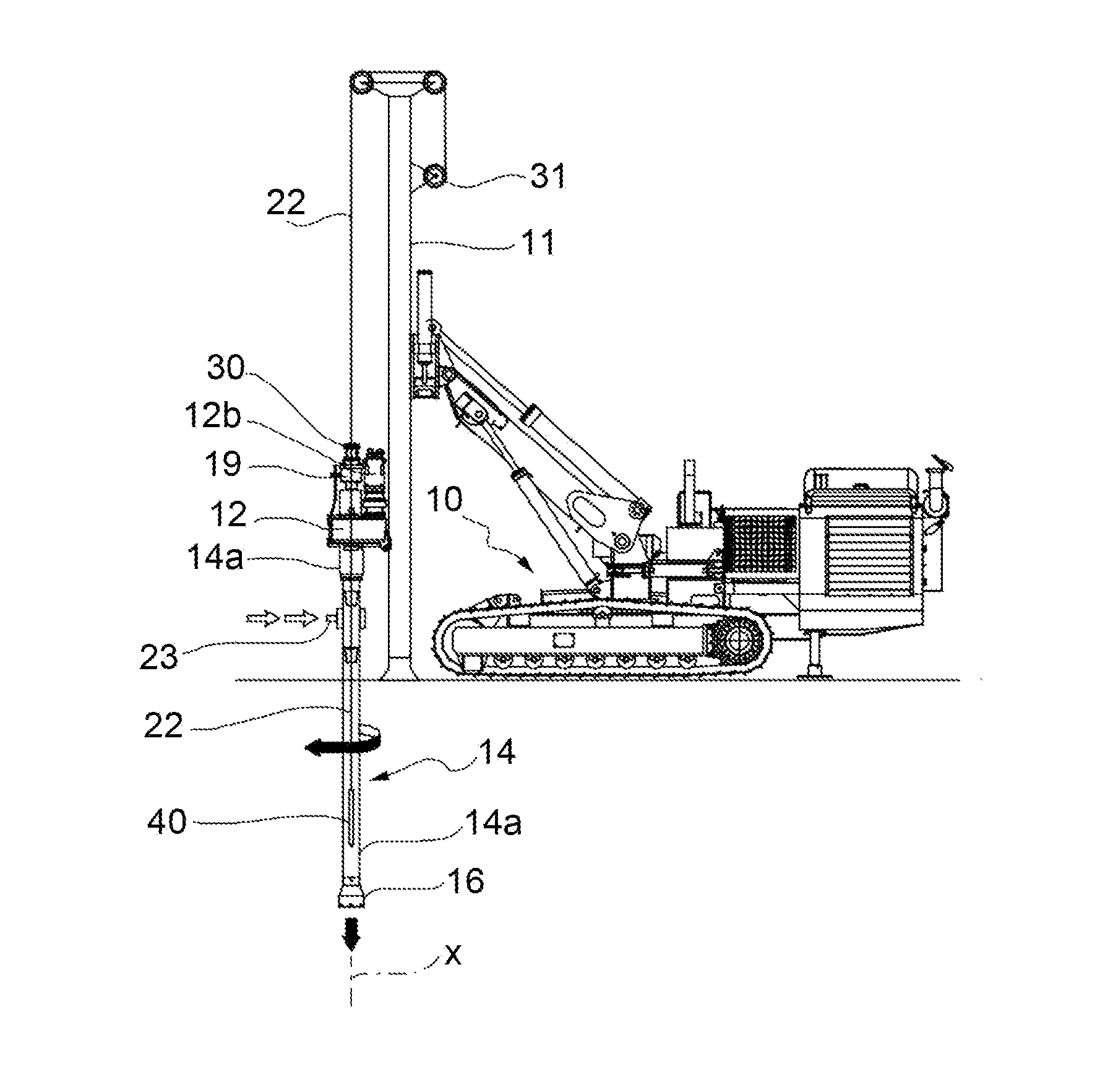
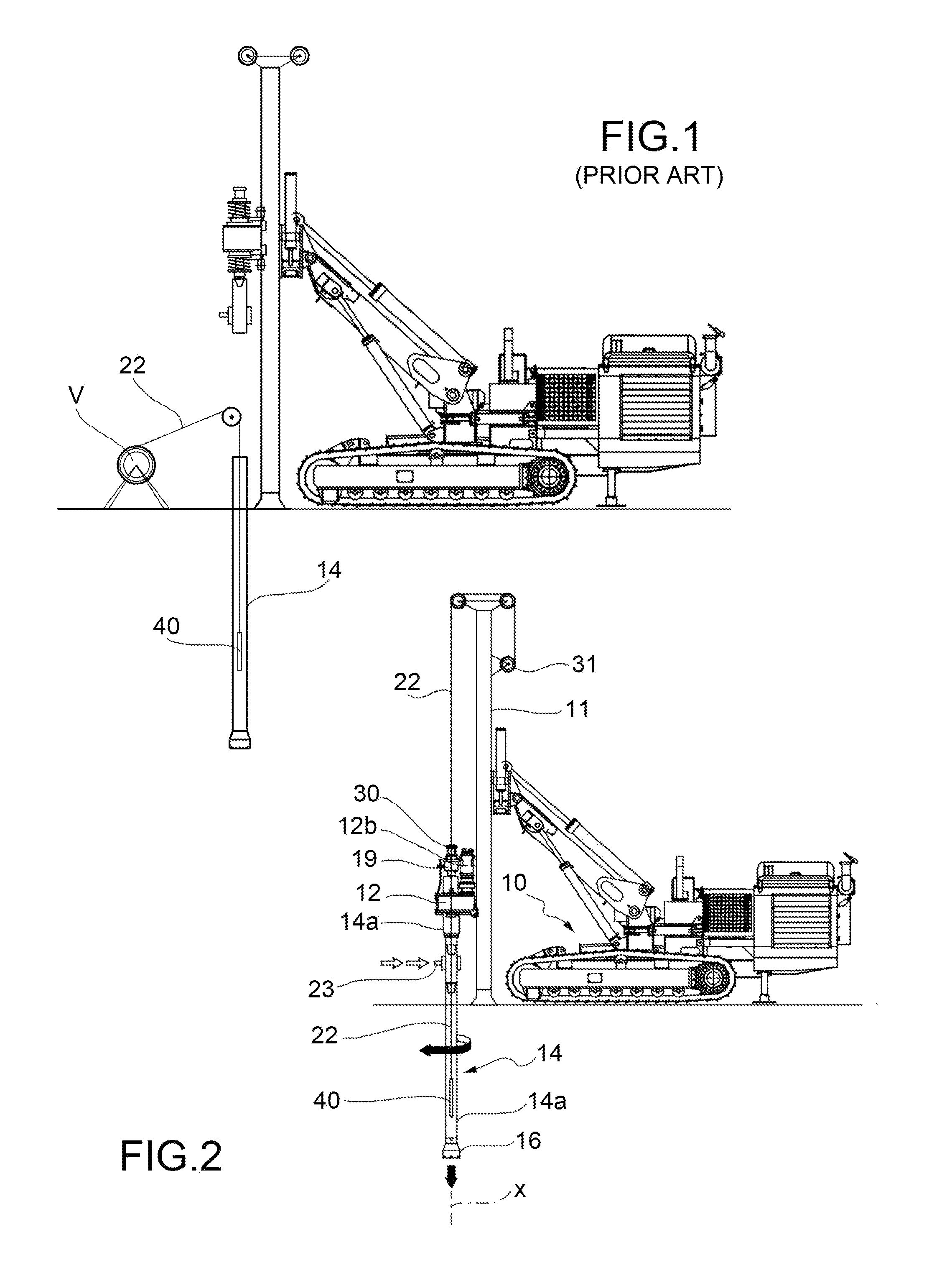
[0022]Referring to FIG. 2, a self-propelled vehicle 10 carries a drilling mast 11, in this example illustrated in an upright or vertical position. Slidably mounted along the mast 11 is a top-drive rotary head 12. The rotary head serves to impart rotation and sliding movement (push-pull) to a string 14 of hollow rods for carrying out soil perforation or drilling. The rotary head may be driven by an associated hydraulic motor gear 12b. A boring tool 16 is fixed at the bottom end of the string 14 of rods.

[0023]The general structure of a drilling mast and of the actuating means of a rotary head are to be considered generally known. Consequently, the present description will describe in detail only those elements of specific importance and interest for the purposes of implementing of the invention. For the construction of the parts and elements not shown in detail, such as the motor assembly for driving the rotary head and the drive systems of the boring tool, reference may be made to an...


PUM


Abstract

A device for measuring inclination is suspended to a cable passing through a duct formed in the rods of the drill string. A mechanism for winding and unwinding the cable allows to raise and drop the measuring device within the lowermost rod, engaging it with or disengaging from a mule shoe. This is performed without the need to unscrew the rods and open the string. A valve element may close the duct through which the cable passes. In one embodiment, directional drilling is performed supplying low pressure fluid through tubular rods having a single duct. In another embodiment, high pressure fluids are supplied through rods having two or more coaxial ducts.

Description

TECHNICAL FIELD[0001]The present invention pertains to the field of civil engineering and relates to a drill rig and methods for performing directional drilling in the ground. The drilling operations are aimed, particularly but not exclusively, at executing jet grouting consolidations.BACKGROUND ART[0002]With soil perforations known as “directional drillings”, deviations are checked at certain phases of the drilling. Corrections are consequently made either to keep the axis of the drilling within certain limits of deviation from the desired theoretical axis, or to keep a given trajectory of the drilling according to design requirements.[0003]In order to detect the inclination during a drilling step, a known method provides for mounting a device for detecting inclination fixedly secured to the bottom of the drill string. A number of electrical connections have to be made as new drill pipes are added, to extend a conductor line from the device up to a power supply on ground surface. U...

Claims


Application Information

Patent Timeline
Patent Type & Authority Applications(United States)
IPC IPC(8): E21B7/06E21B7/02E21B47/024E21B3/02
CPCE21B7/06E21B47/024E21B7/02E21B3/02E21B23/14E04G23/0218E21B23/12E21B3/022
Inventor ANGELICI, MARCO
Owner TREVI
Why Eureka
Try Eureka